Magnet device

a magnetic device and shielding coil technology, applied in the field of magnet devices, can solve the problems of insufficient shielding, low performance of warding off external magnetic flux in imaging space, and long distance between imaging space and shielding coils, etc., and achieve the effect of effectively warding off external magnetic flux

Inactive Publication Date: 2007-03-15
HITACHI LTD
View PDF3 Cites 2 Cited by
  • Summary
  • Abstract
  • Description
  • Claims
  • Application Information

AI Technical Summary

Benefits of technology

[0008] With the magnet device in the open-style MRI apparatus, there unavoidably is a long distance between the imaging space and the shielding coils. For this reason there has been a problem in that the performance of warding off external magnetic flux in the imaging space is low. Simply increasing the number of the turns of winding of these external magnetic field shielding coils in order to strengthen the magnetic fields generated by them leads to a rise in the inductance of the coils. Thus, the electrical current induced by external magnetic fields reduces, and the performance of warding off the external magnetic flux ends up with no increase.
[0009] The object of the present invention, therefore, is to effectively ward off external magnetic flux entering the imaging space of the static magnetic field formed by main coils in a pair positioned facing each other.
[0012] In this case, it is preferable that the second coil group is positioned closer to the static magnetic field space than the first coil group. The intensity of the magnetic fields warding-off the external magnetic flux and generated by the external magnetic flux shielding coils is inversely proportional to the distance. For this reason, positioning the second coil group, which is greater in the coefficient of coil coupling and capable of generating stronger magnetic fields, in a position closer to the static magnetic field allows still effective warding-off of external magnetic flux entering the static magnetic field imaging space.
[0013] Here, it will be more preferable that the external magnetic flux shielding coils are superconducting coils. As a result of this, when the presence of external magnetic flux continues and induced currents continue without reducing, the magnetic fields generated by the external magnetic flux shielding coils continue without reducing, too. Thus the external magnetic flux entering the magnetic field imaging space is effectively warded off.
[0014] Furthermore, a magnet device of the present invention is constructed in such a way that it has main coils in a pair positioned facing each other to form a static magnetic field space in between, an annular coil case for housing the main coils and external magnetic flux shielding coils placed coaxially to said main coils in at least one of an inside and an outside of the coil case, wherein the external magnetic flux shielding coils have a first coil group made up of a plurality of one-turn-coil being winded with a spacing in between and a second coil group made up of a plurality of one-turn-coil having turns of winding with a closer spacing in between than in the first coil group, and said first coil group is connected in series to said second coil group. This, in the same way as the aforementioned, makes it possible to effectively ward off external magnetic flux entering the static magnetic field imaging space.
[0016] According to the present invention, it is possible to effectively ward off external magnetic flux entering the imaging space of the static magnetic field formed by main coils in a pair positioned facing each other.

Problems solved by technology

But in the magnet device of the open-style MRI apparatus having magnetic field sources facing each other and forming a magnetic field imaging space in between, there has been a problem in that it is impossible to obtain sufficient shielding.
With the magnet device in the open-style MRI apparatus, there unavoidably is a long distance between the imaging space and the shielding coils.
For this reason there has been a problem in that the performance of warding off external magnetic flux in the imaging space is low.
Simply increasing the number of the turns of winding of these external magnetic field shielding coils in order to strengthen the magnetic fields generated by them leads to a rise in the inductance of the coils.
Thus, the electrical current induced by external magnetic fields reduces, and the performance of warding off the external magnetic flux ends up with no increase.

Method used


Image

  • Magnet device
  • Magnet device
  • Magnet device

Examples


Embodiment Construction

[0025] The embodiments of a magnet device applying the present invention will be explained based on the drawings as follow.

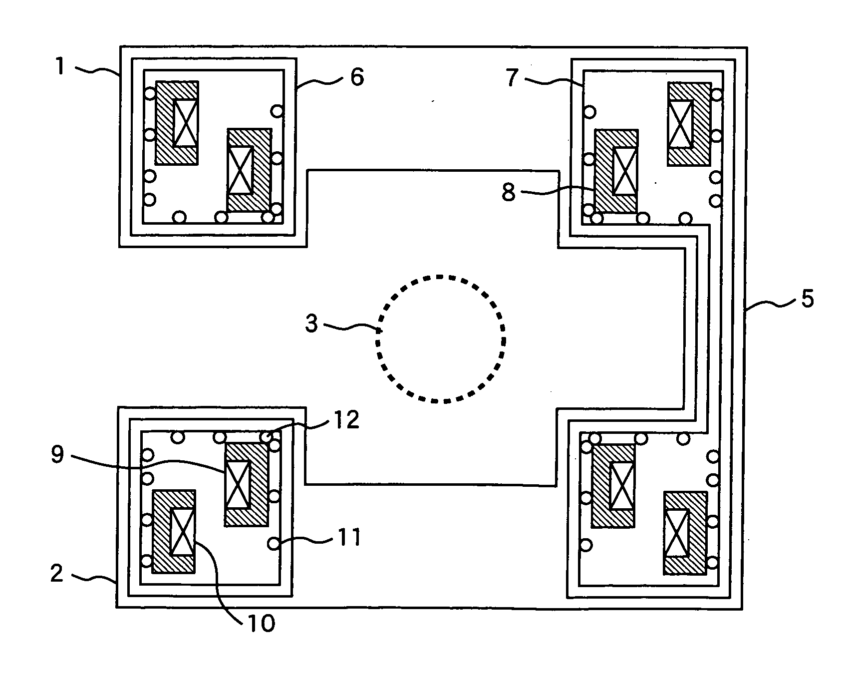
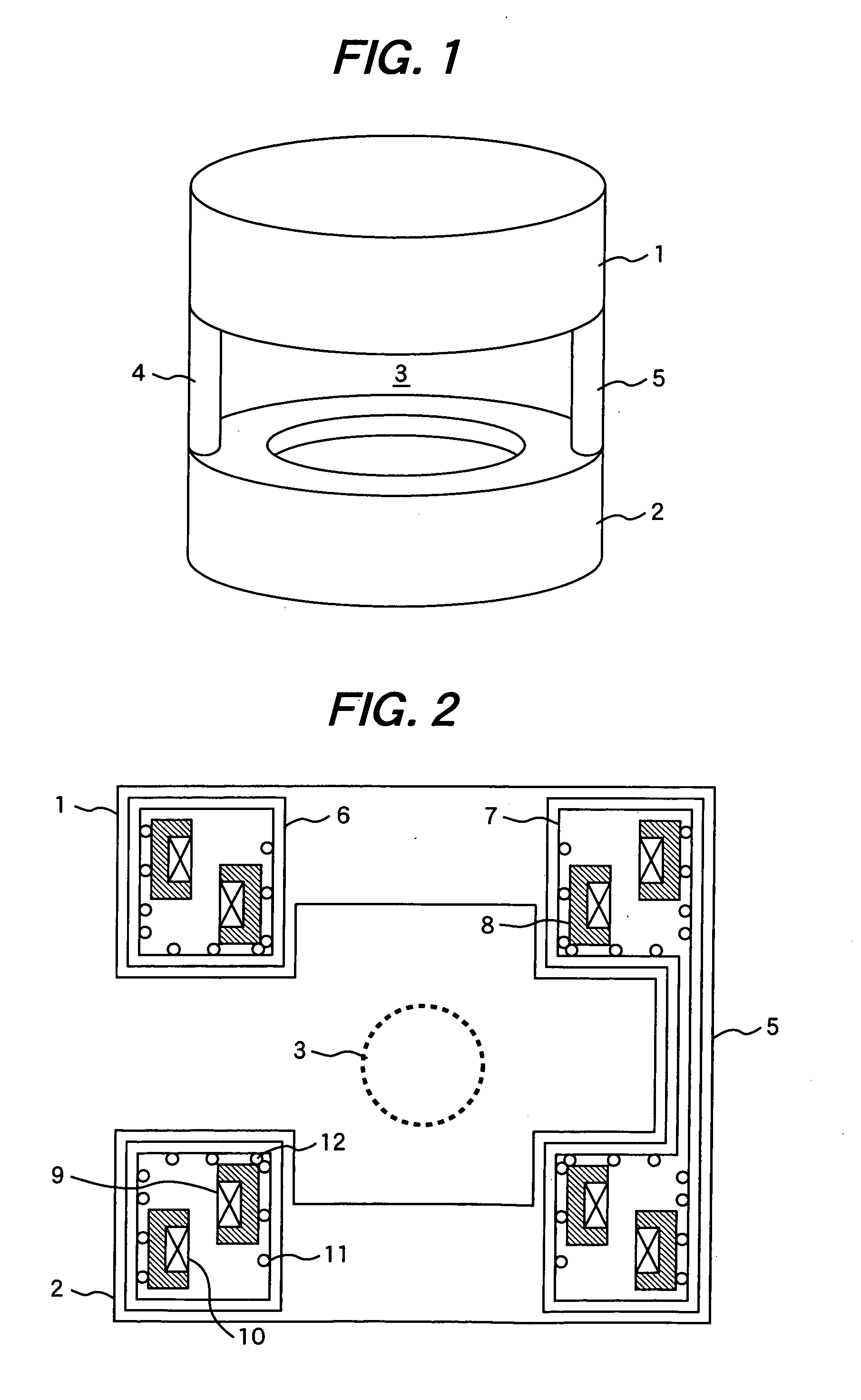
[0026]FIG. 1 is a perspective view of a magnet device of a MRI apparatus in an embodiment 1 of the present invention. FIG. 2 is a vertical sectional view of the magnet device shown in FIG. 1.

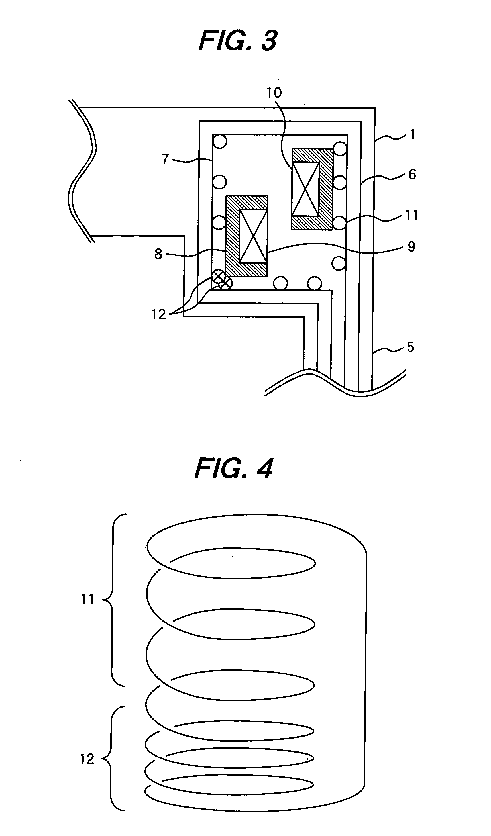
[0027] The magnet device shown in FIG. 1 has magnetic field generation sources 1 and 2 including a pair of main coils and connecting by connecting posts 4 and 5. The magnetic field generation sources 1 and 2 arrange facing each other. The magnetic field generation sources 1 and 2 and the connecting post 5 are housed in a vacuum vessel. A radiation shield 6 is housed in the vacuum vessel. A coil case 7 is housed in the radiation shield 6. The main coils and external magnetic flux shielding coils are housed in the coil case 7 houses, together with such a cooling medium as liquid helium.

[0028] The main coils includes a main magnetic field generation coil 9, and a shield coil...


PUM

PropertyMeasurementUnit
static magnetic fieldaaaaaaaaaa
magnetic fieldaaaaaaaaaa
Magnetic resonance imagingaaaaaaaaaa

Abstract

A magnet device has main coils in a pair positioned facing each other to form a static magnetic field space in between and external magnetic flux shielding coils placed coaxially to the main coils. The external magnetic flux shielding coils have a first coil group having a small coefficient of coil coupling and a second coil group having a coefficient of coil coupling greater than that of the first coil group. The first coil group is connected in series to the second coil group. External magnetic flux entering the magnetic field imaging space formed by main coils in a pair positioned facing each other is effectively warded off.

Description

CLAIM OF PRIORITY [0001] The present application claims priority from Japanese application serial no. 2005-253327, filed on Sep. 1, 2005, the content of which is hereby incorporated by reference into this application. BACKGROUND OF THE INVENTION [0002] The present invention relates to a magnet device, for instance, a magnet device used for magnetic resonance imaging apparatus because of its formation of a static magnetic field space between main coils in a pair positioned facing each other. [0003] Magnetic resonance imaging apparatus uses nuclear magnetic resonance phenomena taking place when a test object (examinee) placed in a static magnetic field space is emitted a high-frequency pulse and thus can obtain images representing the physical and chemical properties of the test object. Accordingly, the magnetic resonance imaging apparatus are now in use particularly for medical purposes. The magnetic resonance imaging apparatus (hereinafter MRI apparatus) are in general made up chief...

Claims


Application Information

Patent Timeline
Patent Type & Authority Applications(United States)
IPC IPC(8): G01N27/84
CPCG01R33/421G01R33/3806
Inventor ANDO, RYUYAABE, MITSUSHINAKAYAMA, TAKESHIYAMAMOTO, TSUTOMU
Owner HITACHI LTD
Why Eureka
Try Eureka