Foam dispenser, housing and storage holder therefor

a foam dispenser and housing technology, applied in the field of foam dispensers, can solve the problems of affecting the health of users, affecting the service life of the foam pump, and the pump and dispenser is not designed to last a long time, so as to achieve the effect of reducing saving the cost of the foam pump

Active Publication Date: 2009-11-03
TECHN CONCEPTS BENTFIELD
View PDF33 Cites 38 Cited by
  • Summary
  • Abstract
  • Description
  • Claims
  • Application Information

AI Technical Summary

Benefits of technology

[0021]When the storage holder needs to be replaced, the coupling piece is released and at least partly pushed out of the adapter by the resilient means. This ensures a more comfortable removal from the storage holder.
[0023]The user of the dispenser, therefore, pumps by exerting a force on the handle. This has the advantage that the operating part of the pump need not be directly operated. On the one hand, this facilitates the use of a handle with a larger operating surface, which is more comfortable in operation. On the other hand, it is thus possible to shield the pump from its surroundings, as it need not be accessible to a user. In this way, contamination of the supply to the air pump, for example, by the wet hands of a user, is avoided.
[0024]The handle may be coupled to the operating part and the foam dispenser further provided with resilient means, supported by the housing and exerting a force opposed to the direction of pumping on the handle. This has the effect of returning the pump to a starting position without leaks after each stroke of the pump, including when the pump starts to move more brusquely towards the end of its lifetime.
[0028]In an embodiment of the storage holder according to the invention, the foam pump has an air passage, of which one end is located in an outer wall of the foam pump facing the reservoir. The coupling piece may be adapted to close off the air passage. This arrangement allows, with the aid of the coupling piece, a pump to be coupled to the fluid reservoir, which is also suitable for hand soap dispensers, wherein the fluid level is below that of the pump and the fluid reservoir is aerated, for instance, because it is not flexible. The advantage is that this pump is manufactured in large series for application in hand soap dispensers. It is efficient and economical to also apply such a pump in the foam dispenser according to the invention.
[0029]According to a further aspect of the invention, the coupling piece is adapted to connect at least two parts of the foam pump to each other. The coupling piece thus also performs the function of keeping together the foam pump. This allows a foam pump to be used which is simpler, so that the costs of the foam pump will be lower.

Problems solved by technology

There is also a chance of contamination from outside, which may block the air supply.
For this reason, the pump and dispenser is not designed to last for a long period of time.
Because the fluid reservoir is located above the level of the pump, parts of the pump continually contact the fluid, due to gravitational effects, and can thus be harmfully affected.
Replacement of the pump entails having to replace the entire housing and is, therefore, costly.
The foam pump may, therefore, be less robust, as the fluid reservoir and pump can both be replaced after use.
A disadvantage of the known apparatus is that the foam pump has been designed especially for this application.
The foam pump is only suitable for application in one sort of housing.
This makes production of the pump much less economical, as it is manufactured in a small series, especially for this application.
When one wants to make different versions of the housing and storage holder, for example, to provide dispensers for different types of fluid, different types of the pump and housing must be made, which further reduces the production series of both the pump and the housing and thus makes manufacturing less economical.

Method used


Image

  • Foam dispenser, housing and storage holder therefor
  • Foam dispenser, housing and storage holder therefor
  • Foam dispenser, housing and storage holder therefor

Examples


Embodiment Construction

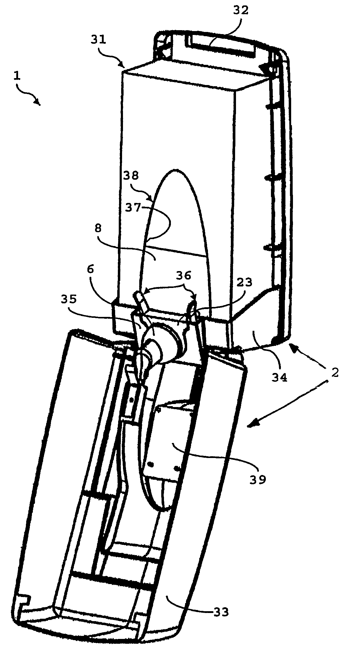
[0041]The invention will be explained with reference to a soap foam dispenser 1. It will be clear that, according to the invention, foaming substances other than soap can also be dispensed. The soap foam dispenser 1 according to the invention is, for example, suited for dispensing a foaming cleaning agent, cosmetics product, etc.

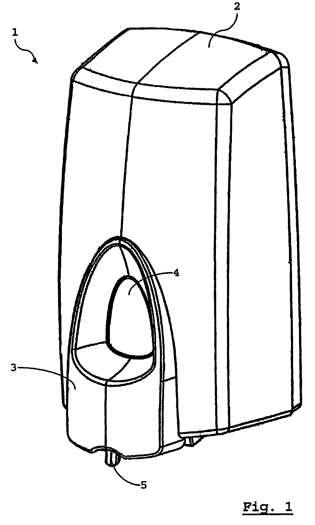
[0042]FIG. 1 shows an example of the soap foam dispenser 1 (also referred to herein as “dispenser 1”). This comprises a housing 2 of which an operating handle 3 forms a part. The housing 2 and the operating handle 3 are preferably made of plastic, e.g., acetal (e.g., POM from BASF), polyamide (PA) or acrylonitrile styrene acrylate (ASA). The operating handle 3 can be made of a plastic different from the housing 2, or have a color different from the housing 2.

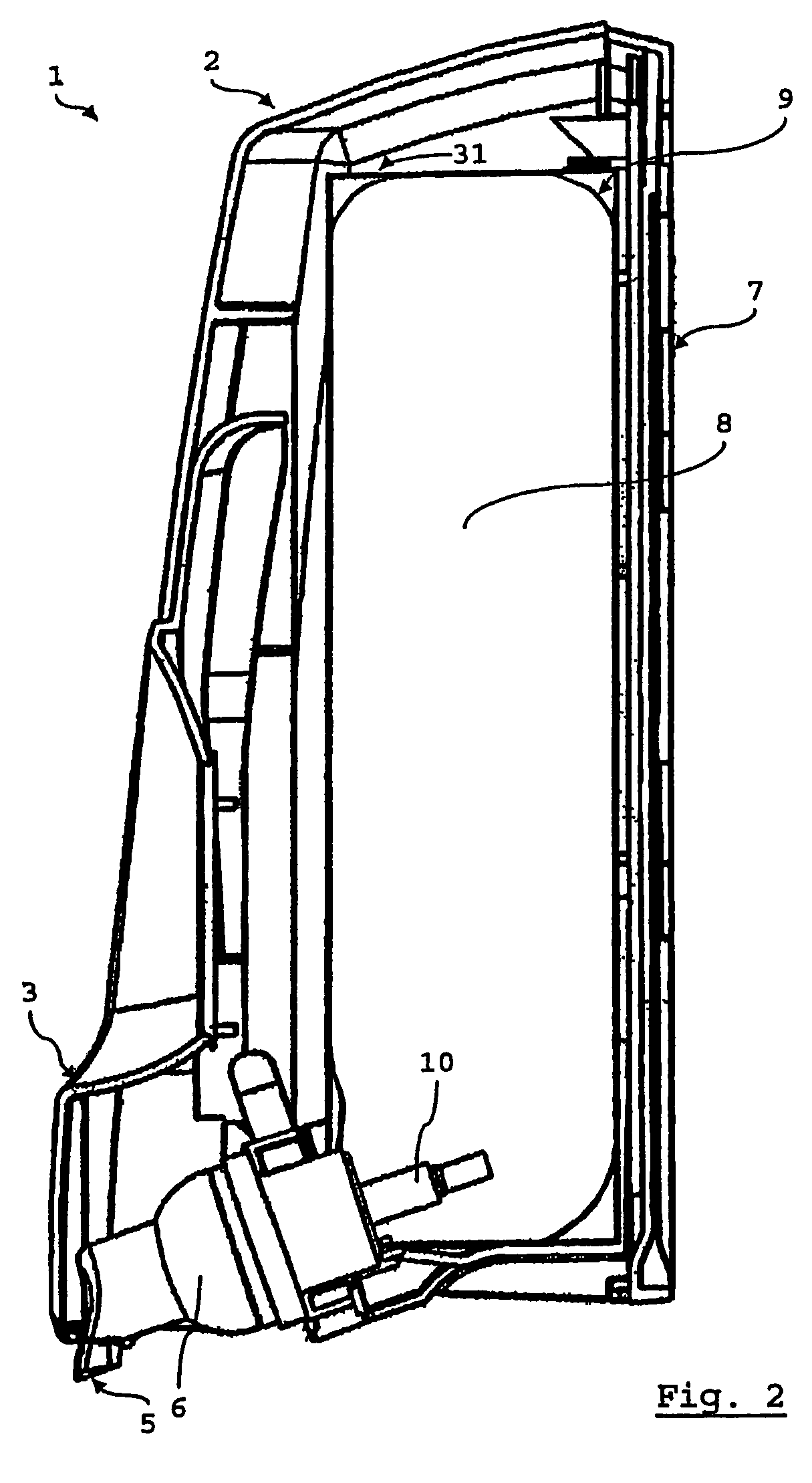
[0043]A window 4 is provided in the operating handle 3. Through the window 4, a view of the contents of a reservoir that is filled with liquid soap is provided. Thanks to the window 4, one can see how fu...


PUM


Abstract

A foam dispenser comprises a housing having an opening, a fluid reservoir placed in the opening of the housing, a plug connected to the fluid reservoir in the opening, and a foam pump, comprising an air pump, a fluid pump, a closable supply to the air pump, a nozzle, and a movable operating part, wherein the foam pump dispenses a quantity of foam through the nozzle upon actuation of the operating part in a direction of pumping, wherein the foam pump and the fluid reservoir are combined into a removable storage holder. The foam dispenser comprises a coupling piece connected to the foam pump, with which the removable storage holder is fastened to the housing.

Description

CROSS-REFERENCE TO RELATED APPLICATIONS[0001]This application is a continuation of PCT International Patent Application No. PCT / NL02 / 00724, filed on Nov. 11, 2002, designating the United States of America, and published, in English, as PCT International Publication No. WO 03 / 059524A1 on Jul. 24, 2003, which claims the benefit of priority to Netherlands Patent Application Serial No. 1019340, filed on Nov. 12, 2001, the contents of both of which are hereby incorporated by this reference in their entireties.BACKGROUND OF THE INVENTION[0002]1. Field of the Invention[0003]The invention relates to a foam dispenser including a housing and a fluid reservoir placed in the housing. The housing includes an opening, a plug connected to the fluid reservoir in the opening, and a foam pump. The foam pump includes an air pump, a fluid pump, a closable supply to the air pump, a nozzle, and a movable operating part and is configured to dispense a quantity of foam through the nozzle upon actuation of ...

Claims


Application Information

Patent Timeline
Patent Type & Authority Patents(United States)
IPC IPC(8): B67D5/58B65D83/76A47K5/14B05B1/02B05B11/00B67D7/76
CPCA47K5/14B05B11/3087B05B11/0043B05B11/3001B05B11/026B05B11/1001B05B11/1087
Inventor GANZEBOOM, WILHELMUS EVERHARDUS
Owner TECHN CONCEPTS BENTFIELD
Why Eureka
Try Eureka