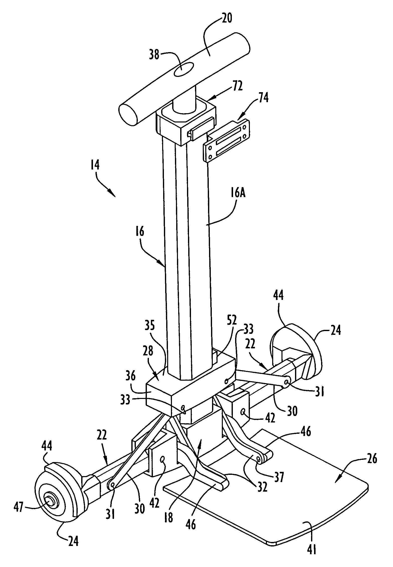
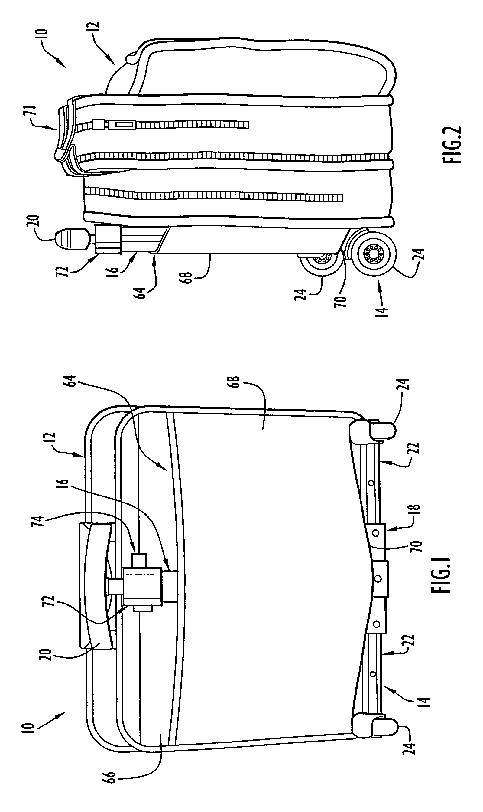
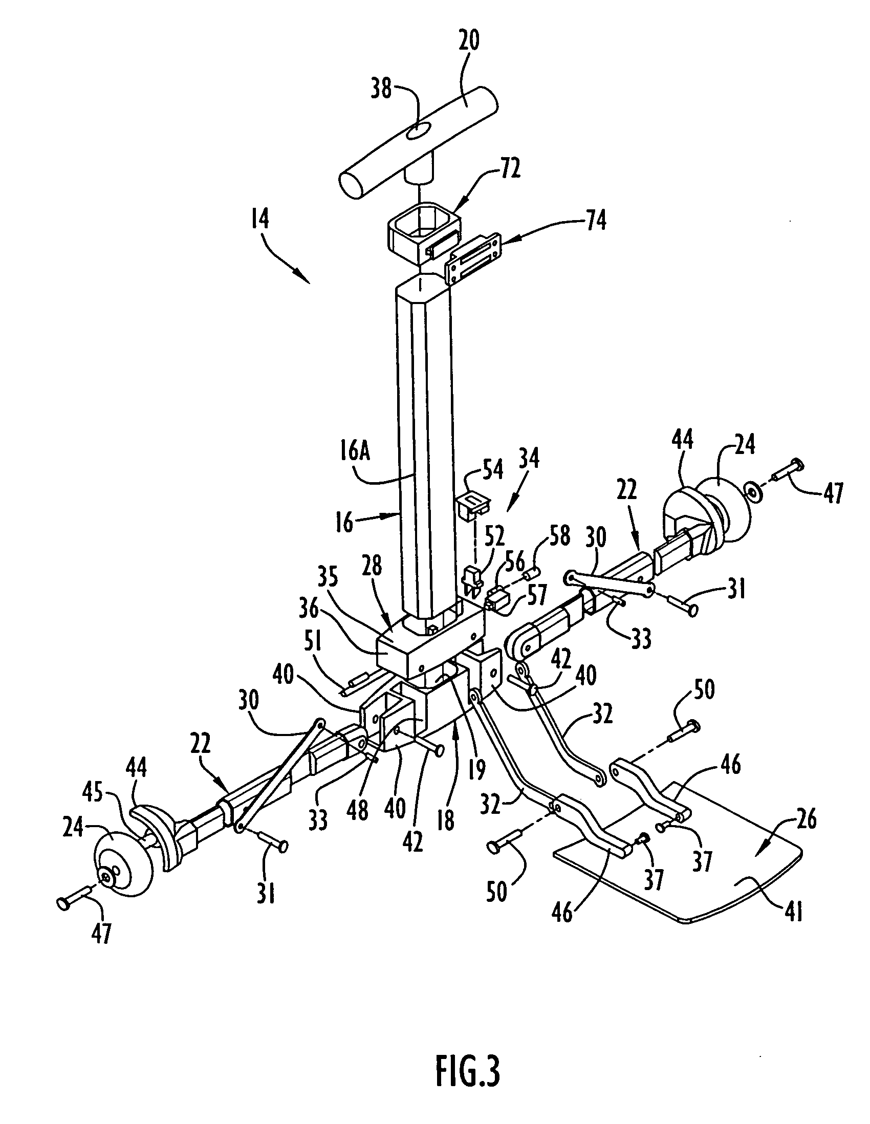
The need to transport non-rolling carrying cases by manual lifting and carrying can be very physically demanding where the carrying cases are relatively bulky and / or heavy and / or must be carried relatively long distances.
Even where non-rolling carrying cases are not especially bulky and / or heavy and / or carried relatively long distances, the act of manually transporting such carrying cases can still be physically demanding for individuals having
physical limitations.
Aside from being physically demanding, manually transporting non-rolling carrying cases by lifting and carrying is oftentimes simply inconvenient for users, and the inconvenience may be compounded where the user has one or more other items to carry at the same time as the carrying case.
The extendable and retractable handles found on rolling carrying cases are necessarily of greater structural complexity than the fixed handles of non-rolling carrying cases.
However when rolling carrying cases are to be used exclusively or primarily as non-rolling carrying cases, i.e. without utilizing the rolling function for a considerable length of time, the wheel structure, the more complex handle structure and / or any other structure associated with the rolling function constitute extraneous components which undesirably add to the weight and / or bulk of the carrying case.
The wheels also present external protuberances which may get caught on and / or damage other objects.
While it would be desirable to remove the wheels of rolling carrying cases when the rolling function is not needed for a considerable length of time, the wheels are typically either permanently attached to or are not quickly and easily removable from the carrying cases.
Accordingly, conventional rolling carrying cases cannot be selectively converted into non-rolling carrying cases and converted back into rolling carrying cases quickly and easily
on demand in accordance with user preferences and needs.
Unfortunately, conventional wheeled luggage carts are in general not designed to facilitate intermittent use of the carrying case as a non-rolling carrying case while the carrying case remains associated with the cart.
Instead, the carrying case must normally be completely disassociated from the wheeled cart, at considerable inconvenience to the user, in order to be used as a non-rolling carrying case even for a brief time.
Nevertheless, many conventional luggage carts have a size and configuration in the collapsed configuration that is too large for the collapsed carts to be stowed in relatively small spaces such as the space beneath an
airplane passenger seat and / or the space within the interior of the carrying cases themselves.
Since the overall width dimension in the expanded operative configuration is oftentimes substantial in size due to various factors including the spacing between the wheels in their deployed position, the inability to decrease the overall width when the carts are placed in the collapsed configuration limits the compactness and portability achieved for the luggage carts in the collapsed configuration.
However, a drawback of these luggage carts and collapsible luggage carts in general relates to the
operational complexity associated with placing the carts in their expanded configurations from their collapsed configurations as well as with placing the carts in their collapsed configurations from their expanded configurations.
Direct manual engagement of the luggage support platforms in order to place the luggage support platforms in their deployed position requires physical
exertion and the awkward use of two hands by the user such that the luggage carts cannot be opened or expanded quickly and easily
on demand.
The
operational complexity associated with placing the carts in the expanded configuration is compounded where a plurality of separate, different, independent and distinct manual operative motions are required.
Furthermore, the physical
exertion, inconvenience and increased time required to place the carts in their expanded configuration from their collapsed configuration are also compounded when a plurality of separate, different, independent and distinct manual operative motions are required.
Accordingly, there is an unfulfilled need for collapsible wheeled luggage carts in which the operational functions needed to deploy the luggage support platforms and the wheels to obtain increased depth and width when placing the carts in the expanded configuration from the collapsed configuration can be effected quickly and easily with minimal effort and inconvenience using a single, simple manual operative motion.
Another
disadvantage of conventional luggage carts relates to the manner in which a carrying case is maintained on the luggage cart.
Where a carrying case is merely supported on the luggage support platform without being structurally or mechanically secured to the luggage cart in any way, the carrying case is at risk of falling off the luggage cart accidentally.
A luggage cart in which the luggage support platform has a width and depth appropriate to support a particular size carrying case may be larger than necessary to support smaller size carrying cases and / or smaller than necessary to support larger size carrying cases, thereby limiting the types and sizes of carrying cases that can be used interchangeably with the luggage cart.
The need for users to apply straps or cords is inconvenient, tedious and
time consuming, and the attachment provided by straps or cords may prove to be unreliable.
The connector elements can be difficult to properly align for interengagement, and engagement and / or release of the connector elements is also made more difficult by their structural and / or
operational complexity.
Where conventional luggage carts are designed for structural or mechanical attachment to a carrying case, the luggage carts and attached carrying cases tend to be lacking in structural continuity and integration in that the luggage carts still appear structurally separate from and not structurally integrated with the attached carrying cases in an aesthetically appealing manner.
Luggage carts which attach to carrying cases oftentimes have physical dimensions which do not correspond proportionally to the attached carrying cases, thereby exacerbating the lack of structural continuity and integration.
In addition, carrying cases that structurally attach to luggage carts are generally not suitable for being manually lifted and carried while remaining attached to the associated luggage cart and are therefore not suitable for use in a manner similar to non-rolling carrying cases unless the carrying case is completely disassociated from the cart.


