
Sticks for athletic equipment

a technology for athletic equipment and sticks, applied in the field of sticks, can solve problems such as sharp points on each side of the fold, metal spall, and eye damage hazards, and achieve the effect of dampening the shock

Inactive Publication Date: 2009-11-10
HAMMER SPORTS
View PDF32 Cites 16 Cited by
  • Summary
  • Abstract
  • Description
  • Claims
  • Application Information

AI Technical Summary

Benefits of technology

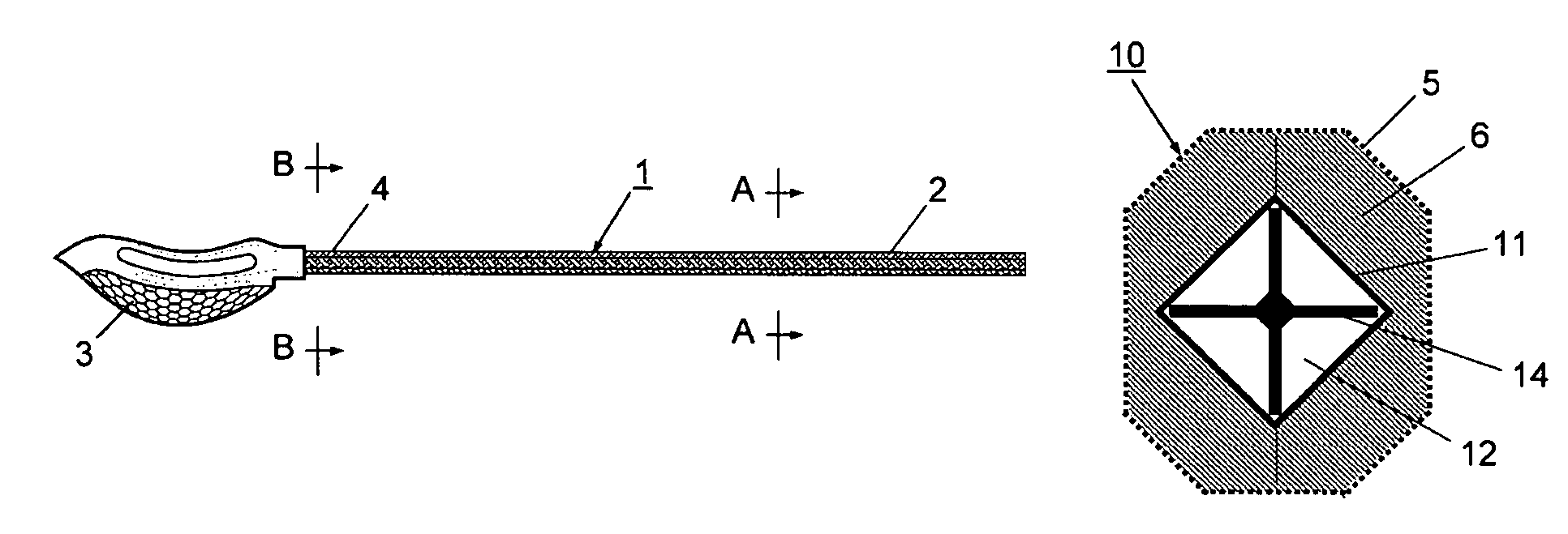
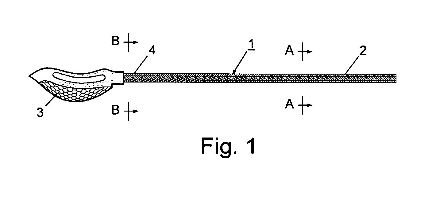
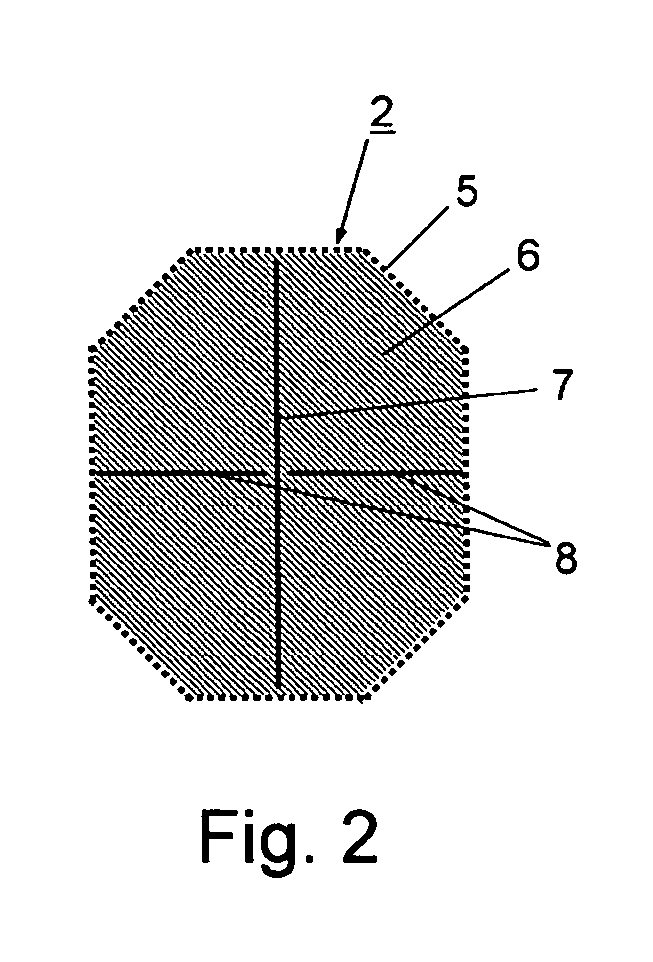
[0004]We have invented a stick for use in playing various sports that overcomes many of the deficiencies of prior sticks. The stick comprises a shaft to which various pieces of athletic equipment can be attached. It has a skin of hard composite resin over a soft foamed plastic core encasing a stiffener. The unique construction of the stick reduces its weight, increases its safety, and improves its behavior when used in playing sports.
[0005]The foamed plastic absorbs shocks and the skin and stiffener provide additional rigidity to the stick. By using a hollow tube as a stiffener, a fixed or moveable weight may be positioned within the hollow tube to enable the user to increase or decrease the weight and / or its position along the tube. A mounting plate at the end of the shaft is provided so that various types of athletic equipment may be attached to the end of the shaft.
[0006]The shaft of this invention is significantly more flexible shaft than the widely available commercial hollow metal or composite tube designs, and the increased flexibility improves safety for the players. For example when a player knocked to the ground has one end of a stick supported by his body with the other end on the ground, and another player falls on the stick, both players benefit from the diminished force applied to their bodies by the more flexible stick.

Problems solved by technology

Commercial hollow metal and composite tube sticks, on the other hand, present sharp points at each side of the fold when bent to folding and, in the case of strong alloys, metal spall has occurred.
Since players do not generally wear eye protection spall could present an eye damage hazard.

Method used


Image

  • Sticks for athletic equipment
  • Sticks for athletic equipment
  • Sticks for athletic equipment

Examples


example 1

Bending Tests

[0045]Bending load testing determined the stress-to-strain measurement under bending and the failure stress, the point of permanent deformation. Additional force was then applied to produce catastrophic failure, or collapse. Measurements were made using a Strike Bender Test Method (SBTM) Machine. This test also measured the elastic stress-strain rate of the shaft that would result from in a Lacrosse ball throwing (shooting) maneuver.

[0046]Using the SBTM, bending stress-strain was determined by mounting a shaft in the hard point bending mounts on a SBTM machine and applying a force perpendicular to the head mounting end. The shafts were mounted to bend across the shorter of the two axes. Force and deflection were measured continuously with incremental increases in the force to establish the stress-strain response until permanent deformation was observed. Upon observing permanent deformation, force was applied to produce catastrophic failure. The results are shown in Tabl...

example 2

Stress-Strain

[0050]Using the data given in Table 2, the stress-strain, the stress at plastic deformation, and the elastic linear stress-strain rate were calculated. Table 3 gives the results.

[0051]

TABLE 3Test Elastic Stress and StrainElasticStress / StrainStressStrainRateSpecimenCore - skin(lbs)(in)(lbs / in)A10.060 inch spar in balsa -182.09no skinA20.030 inch spar in balsa -7.12.82.5no skinA3Round graphite tube in162.46.7balsa - no skinA4Square aluminum tube in62.03balsa - no skinA50.060 inch spar in balsa -332.811.8Kevlar / carbon-Kevlar / carbonA60.030 inch spar in balsa -315.16.1Kevlar / carbon-Kevlar / carbonA7Round graphite tube in balsa -383.511Kevlar / carbon-Kevlar / carbonA8Square aluminum tube in balsa -173.15.5Kevlar / carbon-Kevlar / carbonA9Balsa - Kevlar / carbon-143.54carbon / carbon A10Balsa - carbon / carbon- 122.45carbon / carbon

[0052]The various cores with skin had a significant increase in bending strength over cores without skin. Adding a core stiffening element (A8) to the simple balsa ...

example 3

Structure Failure

[0059]Using the data in Table 3, Table 6 gives the point of structural failure. The test specimens broke without producing sharp jagged edges at the point of failure.

[0060]

TABLE 6Structural FailureStructuralStress-pointstrainfailureratioSpecimenType of core-skinlbsin(lb / in)A50.060 inch spar in balsa -816.712Kevlar / carbon-Kevlar / carbonA60.030 inch spar in balsa -325.95.4Kevlar / carbon-Kevlar / carbonA7Round graphite tube in balsa -505.19.8Kevlar / carbon-Kevlar / carbonA8Square aluminum tube in balsa -287.13.9Kevlar / carbon-Kevlar / carbon

[0061]The core stiffener design affects the amount of force needed to cause structural failure. For the shafts of this invention tested in this program, there was almost a factor of three, from 3.9 to 12 lb / in, difference in the bending stress-strain rate at structural failure.


PUM


Abstract

An elongated shaft has a shock-absorbing core, a fiber-reinforced durable plastic outer skin encasing the core, and an elongated stiffening member encased within the core. The elongated stiffening member may be a spar or a hollow tube. If it is a hollow tube, the tube may contain a weight that moves along the inside of the tube as the shaft is swung. The shaft also has a way to attach athletic equipment, such as a lacrosse head frame and net, to one end.

Description

CROSS-REFERENCE TO RELATED APPLICATION[0001]This invention claims priority from provisional applications Nos. 60 / 710,643 and 60 / 716,911, filed Aug. 23, 2005 and Sep. 14, 2005, respectively, by Rene P. Meyer and Scott D. Patterson.BACKGROUND OF THE INVENTION[0002]This invention relates to a stick having a shaft to which various pieces of athletic equipment can be attached. In particular, it relates to a lacrosse stick having a shock-absorbing core, a durable outer skin encasing the core, and a stiffener encased within the core, and a mounting plate for attaching a lacrosse head frame and net to one end of the shaft.[0003]Lacrosse is a game that originated with the American and Canadian Indians. The game requires a stick to which is attached a small net for catching and throwing a ball. The sticks were originally hand-crafted of wood, usually of hickory, but they lack uniformity as to quality, strength, weight, and feel in the hands of a player. Many modern lacrosse sticks are made of...

Claims


Application Information

Patent Timeline
Patent Type & Authority Patents(United States)
IPC IPC(8): A63B59/02A63B65/12
CPCA63B59/0014F41B15/02A63B59/02A63B59/0092A63B49/08A63B53/10A63B59/0029A63B59/14A63B2209/023A63B2243/005A63B2102/24A63B59/70A63B60/10A63B2102/14A63B60/06A63B59/20A63B60/54A63B60/08A63B60/14
Inventor MEYER, RENE P.PATERSON, SCOTT D.
Owner HAMMER SPORTS
Learn More