Versatile bus interface macro for dynamically reconfigurable designs

a dynamic reconfigurable and bus interface technology, applied in the field of electronic circuit design systems, can solve the problems of restricting the number of reconfigurable modules that may be instantiated, restricting the design of the interface of a given reconfigurable module, and limiting and restricting the design interfa

Active Publication Date: 2009-11-17
XILINX INC
View PDF18 Cites 41 Cited by
  • Summary
  • Abstract
  • Description
  • Claims
  • Application Information

AI Technical Summary

Problems solved by technology

However, tbufs are typically a scarce resource in PLDs, which may restrict the number of reconfigurable modules that may be instantiated in any given design.
Moreover, tbuf macros can only handle a fixed number of signals, which restricts the design of the interface of a given reconfigurable module.
In addition, tbuf macros must be placed at the boundary of the reconfigurable modules, which also limits and restricts the design interface.

Method used


Image

  • Versatile bus interface macro for dynamically reconfigurable designs
  • Versatile bus interface macro for dynamically reconfigurable designs
  • Versatile bus interface macro for dynamically reconfigurable designs

Examples


Embodiment Construction

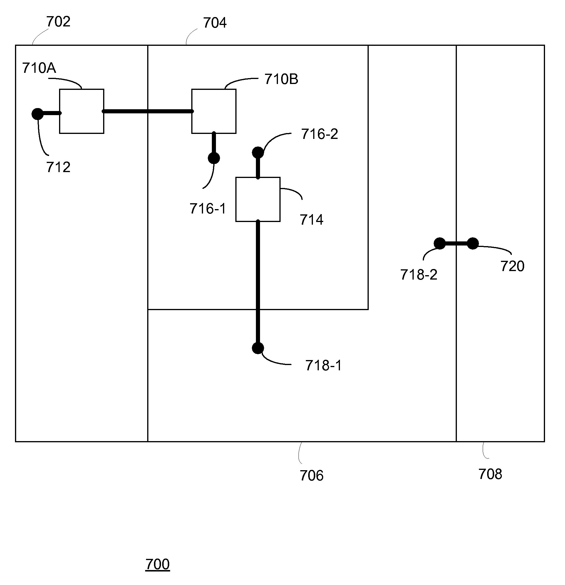
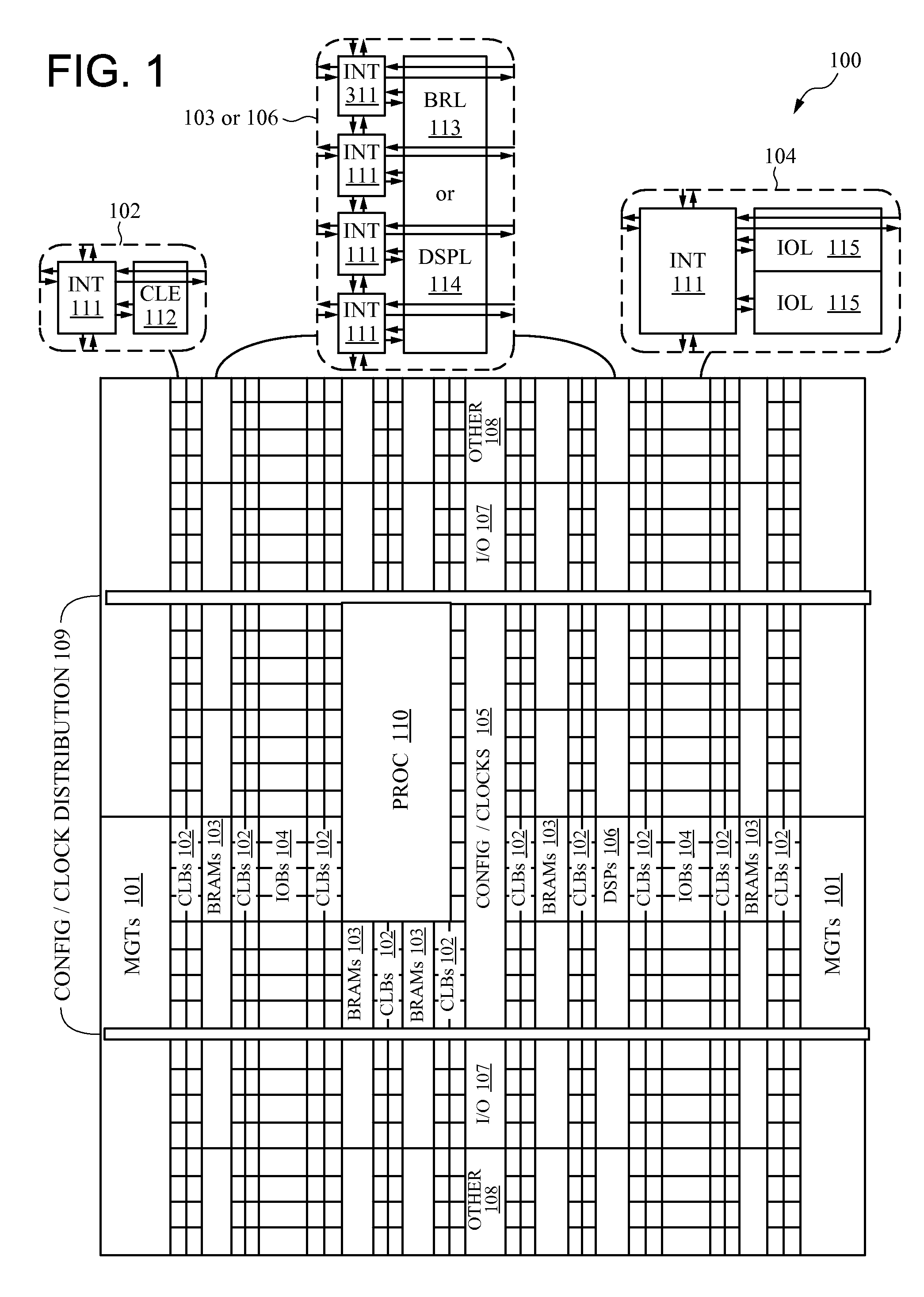
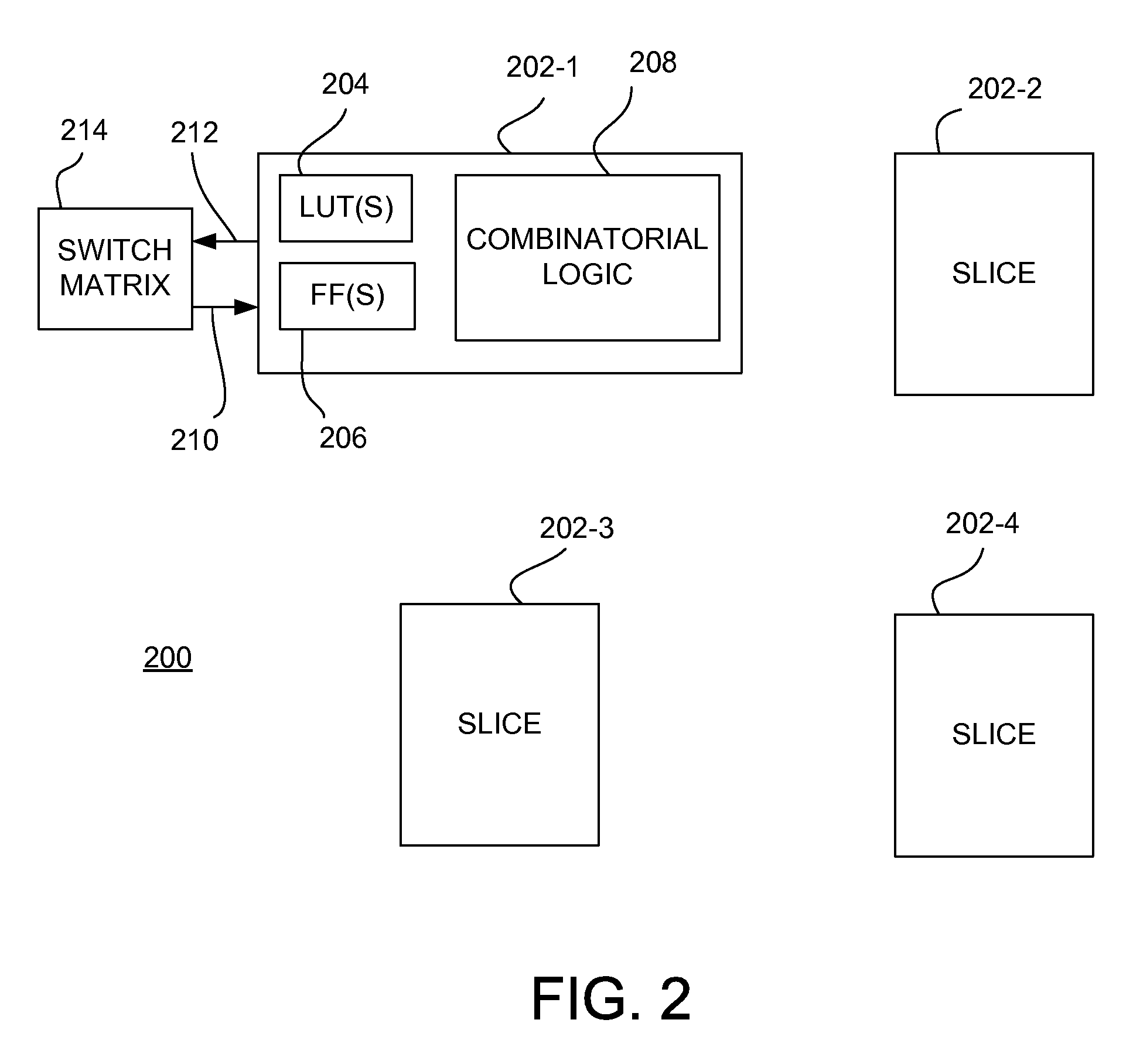
[0013]A versatile bus interface macro for dynamically reconfigurable designs is described. In one embodiment, a logic interface macro includes a single configurable logic block (CLB) slice in a programmable logic device (PLD). The single slice interface macro may be placed anywhere within a reconfigurable module implementation area. The single slice interface macro defines a routing path between two implementation areas, which guarantees that the routing interface between implementation areas (e.g., static and dynamic regions) is fixed. The single slice interface macro improves upon other types of logic interface macros that must be placed along the boundary of the reconfigurable implementation area by allowing the use of more logic interface macros and more optimal placement of such macros. Aspects of the invention may be understood with reference to the following exemplary FPGA and CLB architectures described in FIGS. 1 and 2. Although these architectures are provided by way of ex...


PUM


Abstract

Method and apparatus for module design in a PLD is described. In one example, a PLD includes a reconfigurable module, a static module, and at least one logic interface macro. The reconfigurable module includes a signal interface and is configured for active partial reconfiguration. The static module includes a signal interface. Each logic interface macro includes first pins coupled to the signal interface of the reconfigurable module and second pins coupled to the signal interface of the static module. The first pins and the second pins are disposed in an implementation area of the reconfigurable module. In one embodiment, each logic interface macro includes a slice of a configurable logic block (CLB). In some embodiments, each logic interface macro is implemented using another type of logic block, such as a block RAM and / or multiplier block.

Description

FIELD OF THE INVENTION[0001]One or more aspects of the present invention relate generally to electronic circuit design systems and, more particularly, to a versatile bus interface macro for dynamically reconfigurable designs for programmable logic devices.BACKGROUND OF THE INVENTION[0002]Programmable logic devices (PLDs) exist as a well-known type of integrated circuit (IC) that may be programmed by a user to perform specified logic functions. There are different types of programmable logic devices, such as programmable logic arrays (PLAs) and complex programmable logic devices (CPLDs). One type of programmable logic device, known as a field programmable gate array (FPGA), is very popular because of a superior combination of capacity, flexibility, time-to-market, and cost.[0003]An FPGA typically includes an array of configurable logic blocks (CLBs) surrounded by a ring of programmable input / output blocks (IOBs). The CLBs and IOBs are interconnected by a programmable interconnect str...

Claims


Application Information

Patent Timeline
Patent Type & Authority Patents(United States)
IPC IPC(8): H03K19/173
CPCG06F17/5054G06F30/34
Inventor MASON, JEFFREY M.LEAVESLEY, III, W. STORY
Owner XILINX INC
Why Eureka
Try Eureka