Method and system for automatic stabilization and pointing control of a device

a technology of automatic stabilization and pointing control, applied in the direction of speed measurement using gyroscopic effects, instruments, surveying and navigation, etc., can solve the problem that the device to be pointed is often subject to undesired disturbances

Inactive Publication Date: 2007-07-03
AMERICAN GNC
View PDF3 Cites 21 Cited by
  • Summary
  • Abstract
  • Description
  • Claims
  • Application Information

AI Technical Summary

Benefits of technology

[0015]The main objective of the present invention is to provide a method and system for pointing and stabilizing a device which needs to be pointed and stabilized with a determined orientation, wherein output signals of an inertial measurement unit and the desired direction information are processed to compute platform rotation commands to an actuator; the actuator rotates and stabilizes the device at the desired direction according to the platform rotation commands.
[0016]Another objective of the present invention is to provide a method and system for pointing and stabilizing a device, which needs to be pointed and stabilized at a desired orientation, wherein a visual and voice device is attached to provide a user with visualization and voice indications of targets and the pointing and stabilization operational procedure.
[0017]Another objective of the present invention is to provide a method and system for pointing and stabilizing a device which needs to be pointed and stabilized with a determined orientation, wherein the pointing and stabilization system has increased accuracy that an increase in the system's ability to reproduce faithfully the output pointing direction dictated by the desirable direction.
[0018]Another objective of the present invention is to provide a method and system for pointing and stabilizing a device, which can reduce sensitivity to disturbance, wherein the fluctuation in the relationship of system output pointing direction to the input desirable direction caused by changes within the system are reduced. The values of system components change constantly through their lifetime, but using the self-correcting aspect of feedback, the effects of these changes can be minimized. The device to be pointed is often subjected to undesired disturbances resulting from structural and thermal excitations. To aggravate the problem, disturbance profiles throughout the mission may have different characteristics.
[0019]Another objective of the present invention is to provide a method and system for pointing and stabilizing a device, which is more smoothing and filtering that the undesired effects of noise and distortion within the system are reduced.
[0020]Another objective of the present invention is to provide a method and system for pointing and stabilizing a device, which can increase bandwidth that the bandwidth of the system is defined as a range of frequencies or changes to the input desired direction to which the system will respond satisfactorily.

Problems solved by technology

The device to be pointed is often subjected to undesired disturbances resulting from structural and thermal excitations.

Method used


Image

  • Method and system for automatic stabilization and pointing control of a device
  • Method and system for automatic stabilization and pointing control of a device
  • Method and system for automatic stabilization and pointing control of a device

Examples


Embodiment Construction

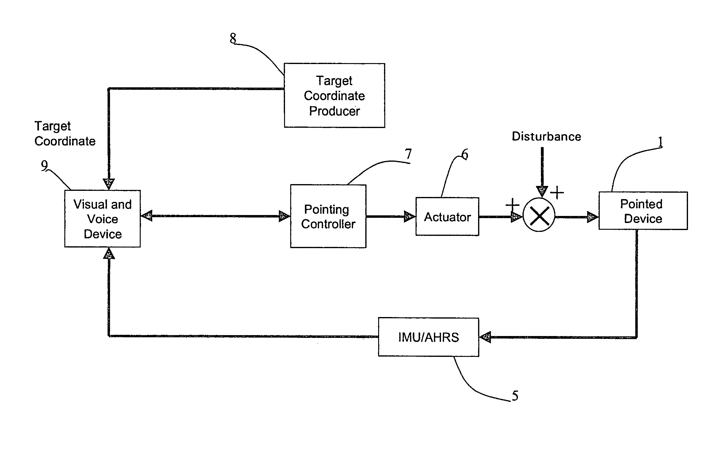
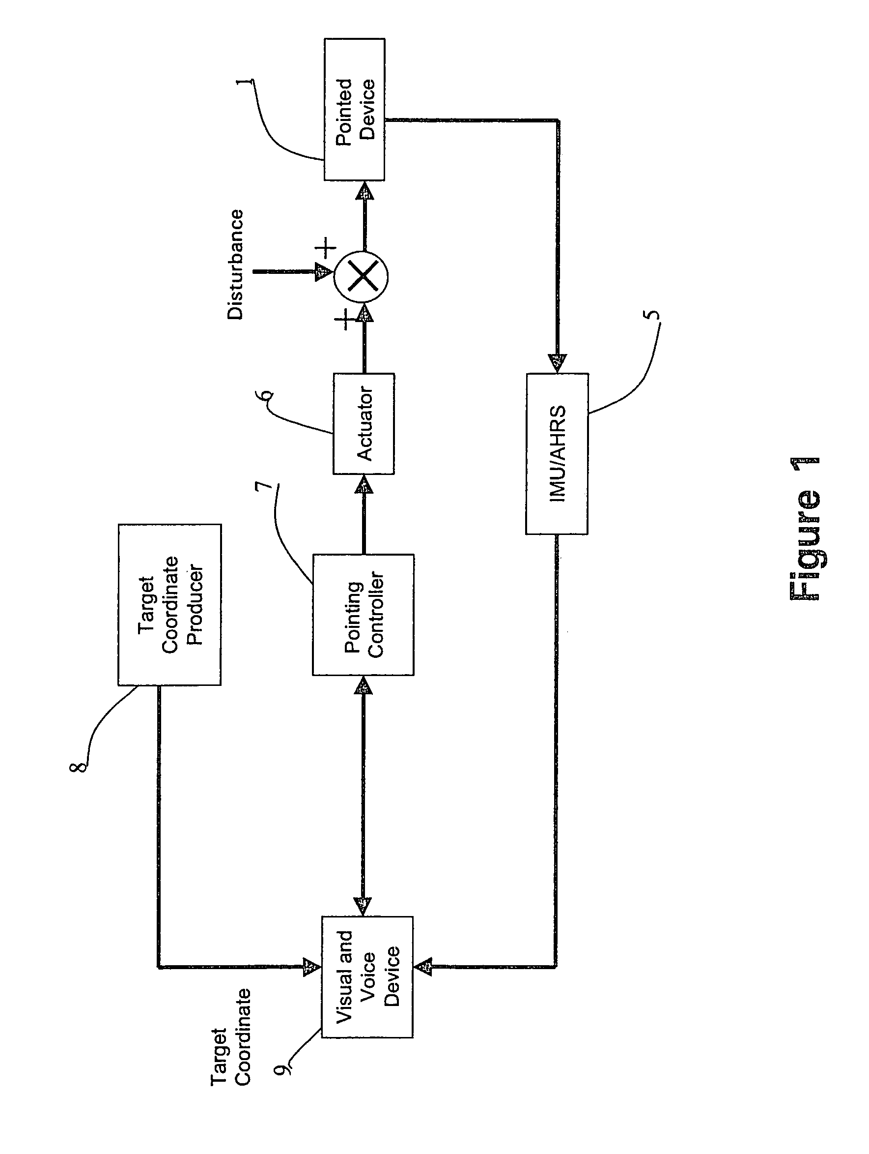
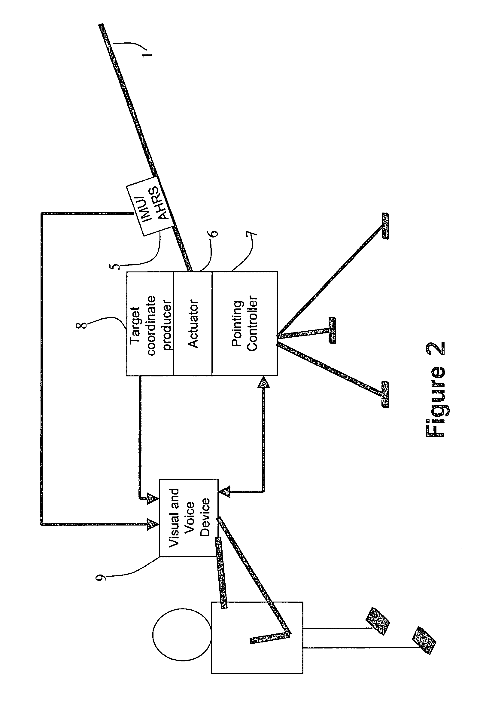
[0041]Referring to FIGS. 1 to 9, a method and system for pointing and stabilizing a device, which needs to be pointed and stabilized at a determined orientation, according to a preferred embodiment of the present invention is illustrated.

[0042]Rapid advance in MEMS technologies makes it possible to fabricate low cost, lightweight, miniaturized size, and low power gyros and accelerometers. “MEMS” stands for “MicroElectroMechanical Systems”, or small integrated electrical / mechanical devices. MEMS devices involve creating controllable mechanical and movable structures using IC (Integrated Circuit) technologies. MEMS includes the concepts of integration of Microelectronics and Micromachining. Examples of successful MEMS devices include inkjet-printer cartridges, accelerometers that deploy car airbags, and miniature robots.

[0043]Microelectronics, the development of electronic circuitry on silicon chips, is a very well developed and sophisticated technology. Micromachining utilizes proces...


PUM


Abstract

The present invention provides a method and system for an innovative design of the automatic stabilization and pointing control of a device based on the MEMS technology, which is small enough and has acceptable accuracy to be integrated into many application systems, such as, laser pointing systems, telescopic systems, imaging systems, and optical communication systems. The stabilization mechanism configuration design is based on utilization of AGNC commercial products, the coremicro IMU and the coremicro AHRS / INS / GPS Integration Unit. The coremicro AHRS / INS / GPS Integration Unit is used as the processing platform core for the design of the MEMS coremicro IMU based stabilization mechanism.

Description

CROSS REFERENCE OF RELATED APPLICATION [0001]This is a regular application of the provisional application having an application number of No. 60 / 667,526 and a filing date of Apr. 2, 2005.BACKGROUND OF THE PRESENT INVENTION [0002]1. Field of the Present Invention[0003]The present invention relates to a controlling method and system for positioning measurement, and more particularly to a method and system for automatic stabilization and pointing control of a device that needs to be pointed at a determined direction, wherein output data of an IMU (Inertial Measurement Unit) installed in the device and target information date are processed to compute a platform rotation command to an actuator; the actuator rotates and stabilizes the device into the determined direction according to the platform rotation commands; a visual and voice device provide a user with visualization and voice indication of the automatic stabilization and pointing control procedure of the device.[0004]The present i...

Claims


Application Information

Patent Timeline
Patent Type & Authority Patents(United States)
IPC IPC(8): G06F15/00
CPCG01C21/18
Inventor COLEMAN, NORMANPAPANAGOPOULOS, GEORGELAM, KENLIN, CHING-FANG
Owner AMERICAN GNC
Why Eureka
Try Eureka