Check patentability & draft patents in minutes with Patsnap Eureka AI!

Method and apparatus for masking a microprocessor execution signature

a microprocessor and execution signature technology, applied in the field of instruction processing in computer systems, can solve the problems of increasing the complexity of the microprocessor, the difficulty of testing (or reverse engineering) the instructions they were executing, and the difficulty of program code testing

Inactive Publication Date: 2009-11-17
ARM FINANCE OVERSEAS LTD
View PDF80 Cites 15 Cited by
  • Summary
  • Abstract
  • Description
  • Claims
  • Application Information

AI Technical Summary

Benefits of technology

"The present invention provides an apparatus and method for disassociating the power consumption of a microprocessor based system from the instructions that it is executing. This is achieved through a power correlator that estimates the power that the microprocessor will consume during execution of instructions, and a subsystem inhibition control that selectively turns on / off ones of the multiple subsystems within the microprocessor during execution of the instructions. This results in the total power consumed by the microprocessor being unrelated to the instructions that it is executing. The invention also provides a computer program product for use with a computing system and a method for disassociating power consumption from instructions."

Problems solved by technology

With the advent of the microprocessor, testing of program code, and reverse engineering of program code, became more difficult.
As the complexity of microprocessors increased, so did the difficulty of testing (or reverse engineering) the instructions they were executing.
For example, modern processors, although they have external data and address buses, cannot successfully be probed to determine what instructions are executing.
So, examination of the external data / address buses during the transfer does not provide any direct correlation to the instructions that are executing.
The reverse engineer, however, has no access to the internal model of a processor that s / he is trying to decode.
In many cases, such reverse engineering can have devastating consequences.

Method used


Image

  • Method and apparatus for masking a microprocessor execution signature
  • Method and apparatus for masking a microprocessor execution signature
  • Method and apparatus for masking a microprocessor execution signature

Examples


Embodiment Construction

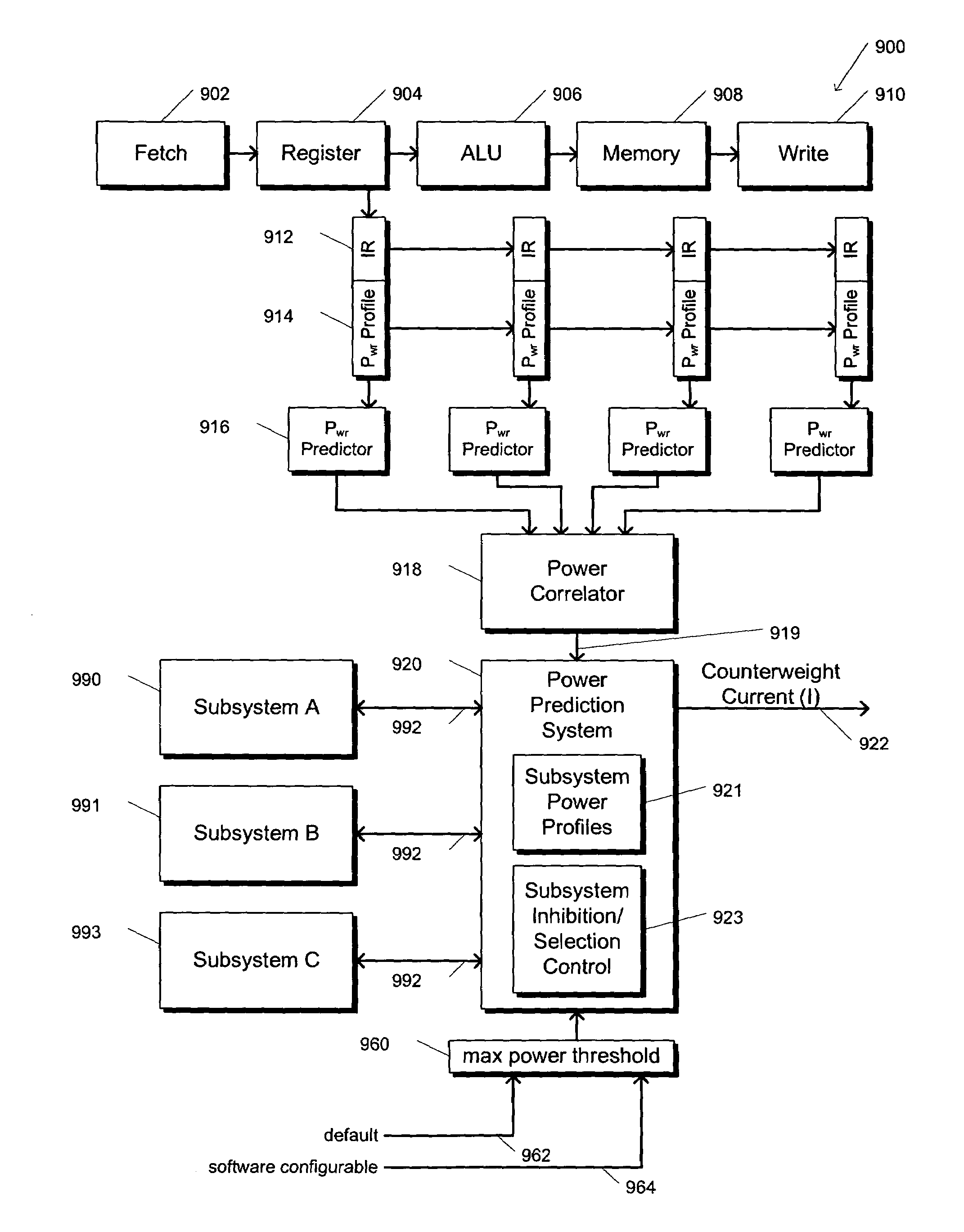
[0036]Referring to FIG. 1, a block diagram of a microprocessor based system 100 is shown to illustrate a prior art method of determining what instructions are executing on a microprocessor. The method utilizes a technology referred to as differential power analysis. More specifically, a microprocessor 102 is shown attached to a differential power analyzer 104 via current probes 106. In most instances, the differential power analyzer 104 is a current monitor that is capable of measuring current drain on selected pins of the microprocessor 102, on a continuous basis. Since the voltage is constant, power consumed by the microprocessor 102 may be determined by measuring the current drawn on each of its power supply pins. A graph 108 is shown illustrating the cumulative current (measured along the y-axis) drawn by the microprocessor 102 during consecutive clock cycles (measured along the x-axis). Also shown are two scientists 110 examining the chart 108 to try to understand what the micr...


PUM


Abstract

An apparatus and method are provided that disassociates the power consumed by a processing system from the instructions that it executes. The apparatus includes a power predictor that predicts the power that will be consumed by the processing system during execution of particular instructions, and a subsystem inhibition control, that selectively turns on / off available subsystems within the processing system based on the power that is predicted to be consumed. By predicting the power that will be consumed during execution, and by selectively turning on / off particular subsystems, the total power consumed by the processing system can be made invariant, or random. In either case, a counterweight current can be added to the processing system, depending on which of the subsystems are available to be turned on / off, and which are turned on / off, to further disassociate the total power consumed by the processing system from the instructions it is executing.

Description

CROSS REFERENCE TO RELATED APPLICATION(S)[0001]This application is a continuation of U.S. patent application Ser. No. 09 / 894,812, filed Jun. 28, 2001 now U.S. Pat. No. 6,976,178, entitled “A METHOD AND APPARATUS FOR DISASSOCIATING POWER CONSUMED WITHIN A PROCESSING SYSTEM WITH INSTRUCTIONS IT IS EXECUTING”, which is a continuation-in-part of U.S. patent application Ser. No. 09 / 665,099 filed Sep. 20, 2000, now U.S. Pat. No. 6,625,737, entitled “SYSTEM FOR PREDICTION AND CONTROL OF POWER CONSUMPTION IN DIGITAL SYSTEMS”, both commonly assigned to MIPS Technologies, Inc.BACKGROUND OF THE INVENTION[0002]1. Field of the Invention[0003]This invention relates in general to the field of instruction processing in computer systems, and more particularly to an apparatus and method in a CPU for predicting power consumption for executing instructions and counterbalancing or randomizing total power consumption for security purposes by turning on or shutting down selected subsystems.[0004]2. Descri...

Claims


Application Information

Patent Timeline
Patent Type & Authority Patents(United States)
IPC IPC(8): G06F1/32G06F1/26
CPCG06F21/81G06F21/75G06F21/755
Inventor KISSELL, KEVIN D.
Owner ARM FINANCE OVERSEAS LTD
Features
  • R&D
  • Intellectual Property
  • Life Sciences
  • Materials
  • Tech Scout
  • Unparalleled Data Quality
  • Higher Quality Content
  • 60% Fewer Hallucinations
Learn More