Medical/surgical waste collection unit including waste containers of different storage volumes with inter-container transfer valve and independently controlled vacuum levels

a waste collection and medical device technology, applied in the direction of suction drainage containers, packaging, other medical devices, etc., can solve the problems of increasing the number of waste collection units, and increasing the number of users

Active Publication Date: 2009-11-24
STRYKER CORP
View PDF40 Cites 299 Cited by
  • Summary
  • Abstract
  • Description
  • Claims
  • Application Information

AI Technical Summary

Benefits of technology

[0014]The present invention provides a waste collection unit for collecting waste material during a series of medical procedures. The waste collection unit includes first and second waste containers. The first waste container has a maximum storage volume. The second waste container has a maximum storage volume larger than the maximum storage volume of the first waste container. The first waste container is adapted for connection to one suction line to collect the waste material in the first waste container during a medical procedure. The second waste container is adapted for connection to another suction line to collect the waste material in the second waste container during the medical procedure. A vacuum source is in selective communication with the waste containers to provide a vacuum in the waste containers and draw the waste material into the waste containers through the suction lines during the medical procedure. A transfer valve is disposed between the waste containers. In the open position, the transfer valve allows the waste material in the first waste container to flow into the second waste container. This feature of the waste collection unit of this invention reduces the number or trips that a user has to make between use areas in which the waste material is being collected (such as an operating room) and the docking station, which is typically located outside of the use area.
[0017]By providing independently controlled vacuum levels in the waste containers, the waste collection unit can be employed in those instances in which it is necessary to use a plurality of suction lines of varying suction to draw waste materials from a plurality of sites during a single medical procedure. As medical procedures continue to advance, there may be an increasing need to provide different suction levels in the suction lines during the same medical procedure. In addition, the first and second vacuum regulators of the present invention are designed to provide independently controlled vacuum levels in the waste containers from a single vacuum source. This eliminates the need for separate vacuum pumps to draw different vacuum levels in the waste containers.
[0018]A filter and float assembly is also provided in one or more of the waste containers to prevent water droplets and waste material from entering the vacuum source and potentially fouling the vacuum source. The waste container defines a collection chamber, a filter compartment, and a vacuum port opening into the filter compartment. The vacuum source is in communication with the vacuum port of the waste container to provide a vacuum in the waste container to draw the waste material into the waste container through the suction line(s). The filter and float assembly is disposed in the filter compartment adjacent to the vacuum port. The filter and float assembly comprises a filter element disposed between the vacuum port and the collection chamber for removing moisture from fluid entering into the vacuum port from the collection chamber. The filter and float assembly also includes a retaining member to secure the filter element in position. The retaining member defines a sleeve. A float is slidably supported in the sleeve to prevent the waste material collected in the waste container from entering into the vacuum port when a level of the waste material exceeds a predetermined threshold.
[0019]In another aspect of the present invention, a connector is used to connect a vacuum line to a cap of the first waste container. The connector is coupled to the vacuum line and is seated in a corresponding receptacle in the cap. A first retainer is rotatably supported by the cap for rotating between a locked position to retain the first connector in the first receptacle and an unlocked position to release the first connector from the first receptacle. By utilizing this quick-release, the waste collection unit can be quickly and easily serviced. Otherwise, if conventional connectors were used, it may take several minutes to release the connectors from the cap to service the vacuum circuit or other systems of the waste collection unit.
[0027]A docking station is also provided for disposing of the waste material collected by the waste collection unit and for cleaning the waste containers. The waste collection unit is outfitted with a carrier for holding a first plurality of couplings that are in communication with the waste containers and with a cleaning system on the waste collection unit. The docking station is fixed at a location in a health care facility. The docking station includes a cabinet. A head extends from the cabinet. The head includes a second plurality of couplings for mating with the first plurality of couplings. A mating interface carries the second plurality of couplings and moves the second plurality of couplings upwardly, relative to gravity, to make the connection to the first plurality of couplings. The head includes a floating frame carrying the mating interface for engagement by the carrier such that the floating frame aligns the second plurality of couplings with the first plurality of couplings when engaged by the carrier to facilitate mating of the couplings. By moving the second plurality of couplings upwardly, the waste collection unit can be wheeled over top of the head such that the connection of the couplings is largely hidden from view. Furthermore, by providing the floating frame, alignment of the couplings is made possible prior to moving the second plurality of couplings upwardly.
[0030]A power coupler is also provided for transferring electric power from the docking station to the waste collection unit. The power coupler includes a first winding supported by the docking station and electrically connectable to a fixed power source. The power coupler further includes a second winding supported by the waste collection unit and inductively coupleable to the first winding when the waste collection unit is docked to the docking station. The power coupler provides for operation of the waste collection unit without requiring an on-board battery on the waste collection. By coupling power from a fixed power source to the waste collection unit, time and costs can be saved.

Problems solved by technology

If a series of medical procedures are performed in which it is necessary to empty the waste container before each procedure, the user could find it annoying to have to continuously wheel the waste collection unit back and forth between a use area, such as an operating room, and the docking station, which is typically situated outside of the operating room in a hallway near a waste drain.
Thus, these containers are relatively large in size.
However, a disadvantage of providing a waste collection unit with a small container, for example one capable of storing 10 or less liters of waste would mean that the container would become filled more quickly.
This would then result in the interruption of the procedure in order to empty the waste collection unit.
However, these units are also susceptible to water droplets that may enter the vacuum source inadvertently before the waste material rises to the predetermined threshold level in the waste container.
Once the hoses are connected to the barbed nozzles, they are difficult to remove for servicing.
The known prior art volume measuring systems do not take into account variations in volume due to temperature or variations in volume due to the manufacturing of each container.
Unfortunately, these blowers, when operating, tend to be noisy, and thus distracting to medical personnel performing the medical procedures.
Unfortunately, the height of such IV poles often prohibits medical personnel of a smaller stature from reaching the top of the IV pole to hang the IV bags.
Furthermore, the IV poles are prone to damage from doorways and other structures when the waste collection unit is moved.
When off-loading the waste material, the first pair of couplings can become dirtied with waste material, and since they are externally disposed on the front of the waste collection unit, can be unsightly.

Method used


Image

  • Medical/surgical waste collection unit including waste containers of different storage volumes with inter-container transfer valve and independently controlled vacuum levels
  • Medical/surgical waste collection unit including waste containers of different storage volumes with inter-container transfer valve and independently controlled vacuum levels
  • Medical/surgical waste collection unit including waste containers of different storage volumes with inter-container transfer valve and independently controlled vacuum levels

Examples


Embodiment Construction

I. Overview

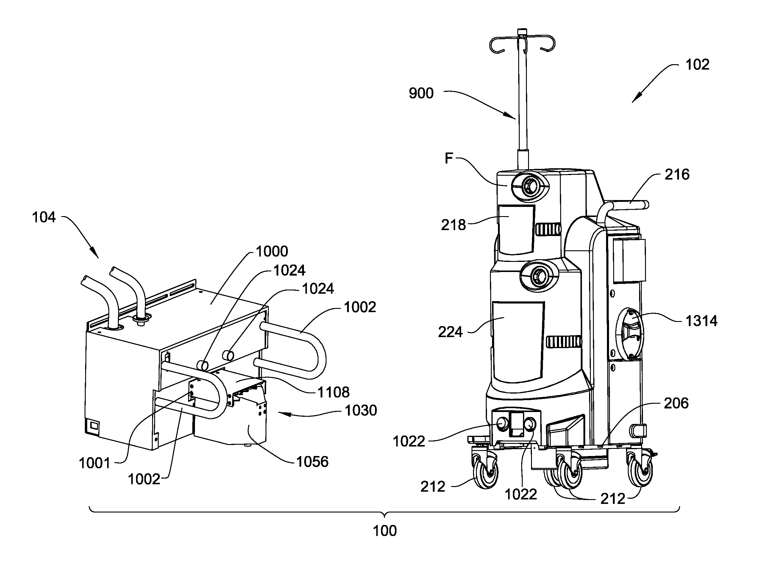
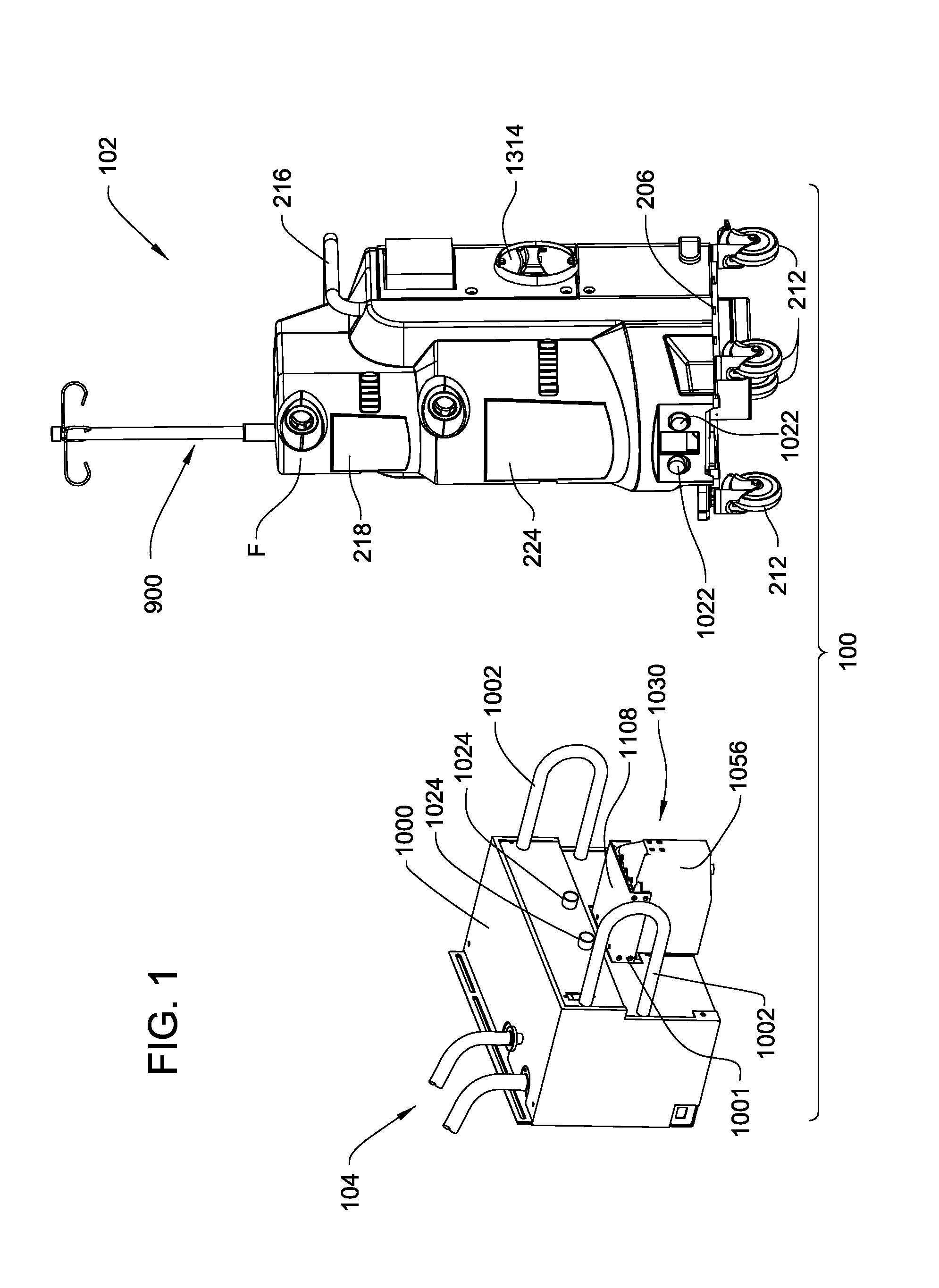
[0110]Referring to the Figures, wherein like numerals indicate like or corresponding parts throughout the several views, a waste collection and disposal system for collecting and disposing of waste materials is shown generally at 100. The system 100 collects and disposes of waste material generated during medical procedures (e.g., surgical procedures) performed in a health care facility such as a hospital. The waste material may include bodily fluids, body tissues, irrigation liquids, and / or other materials that may be generated during various medical procedures. Often times, medical procedures require large amounts of saline and / or other irrigation liquids for irrigating an anatomical site. As a result, the system 100 is capable of handling large amounts of waste material.

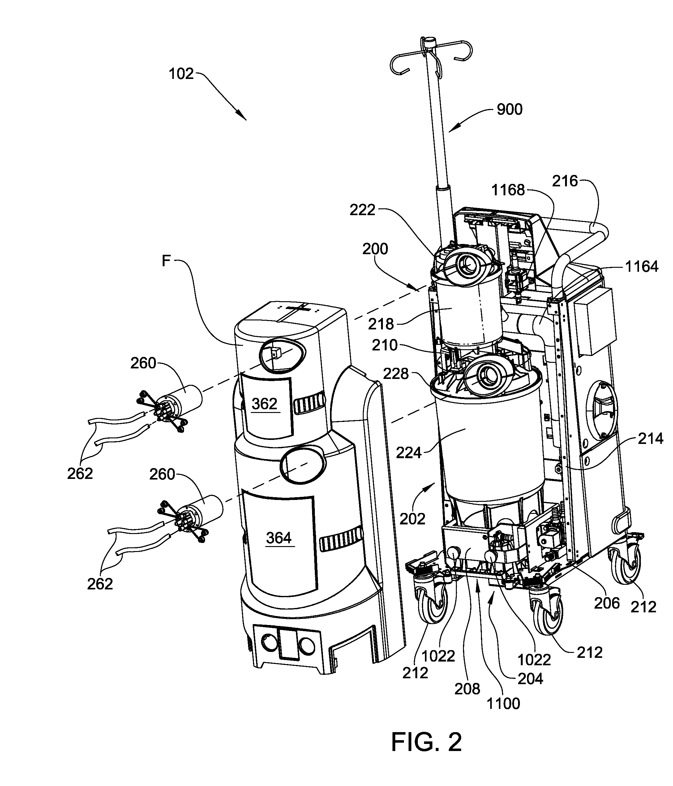
[0111]Referring to FIG. 1, the system 100 comprises a mobile waste collection unit 102 and a fixed docking station 104. The waste collection unit 102 collects the waste material generated during the med...


PUM

PropertyMeasurementUnit
storage volumeaaaaaaaaaa

Abstract

A waste collection and disposal system for use in health care facilities is provided. The system includes a mobile waste collection unit for moving between use areas in the health care facility to collect waste material generated during medical procedures including body fluids, body tissues, saline, etc. The waste collection unit includes stacked upper and lower waste containers for receiving the waste material. During use, the upper waste container can be emptied into the lower waste container for temporary storage. In addition, different vacuum levels can be provided in the waste containers during complex procedures. Once a user desires to empty the waste collection unit, the waste collection unit is wheeled to a docking station. At the docking station, the waste material is off-loaded to a waste drain and the waste collection unit is cleaned and rinsed for further use.

Description

CROSS-REFERENCE TO RELATED APPLICATIONS[0001]This application claims the benefit of U.S. provisional patent application Ser. No. 60 / 750,862, filed on Dec. 14, 2005, the advantages and disclosure of which are hereby incorporated by reference.FIELD OF THE INVENTION[0002]The present invention relates to a waste collection and disposal system for collecting and disposing of waste materials, such as bodily fluids, generated during medical procedures carried out in a health care facility, e.g., a hospital. More specifically, the present invention relates to a waste collection unit for collecting the waste material and a docking station for disposing of the waste material from the waste collection unit and cleaning the waste collection unit for further use.BACKGROUND OF THE INVENTION[0003]Waste collection and disposal systems are well known for use in health care facilities to collect waste material generated during medical procedures. Examples of such systems can be found in U.S. Pat. No....

Claims


Application Information

Patent Timeline
Patent Type & Authority Patents(United States)
IPC IPC(8): A61M1/00F24F8/108F24F8/158
CPCA61M1/0052A61M1/0005A61M1/0023A61M1/0031A61M1/0049A61M1/0056A61M1/0058B01D46/0036B01D46/442F24F3/1603A61M1/0027A61M1/0007A61M1/0033A61M1/0035A61M1/005A61M1/0001A61B2218/006A61M2205/125A61M2205/3331A61M2205/3355A61M2205/52A61M2205/707A61M2205/7545A61M2205/7563A61M2209/082A61M2209/084A61M2209/086A61M1/631A61M1/732A61M1/63A61M1/742A61M1/743A61M1/782A61M1/78A61M1/79A61M1/784A61M1/74A61M1/60A61M1/73A61M1/77A61M1/71F24F8/158F24F8/108A61M5/1415A61M2205/584A61M2205/587Y10T137/3109A61M2205/35A61M3/0201A61M1/72B01D53/02B01D53/025B01D53/30
Inventor LALOMIA, BRENT S.REASONER, STEPHEN J.ISHAM, STEPHEN P.GAMHEWAGE, CHAMARAWASSERMAN, MARK A.ROCQUE, GLEN D.DURNELL, TROY E.WESTPHAL, GRANT T.MACLACHLAN, BRIAN
Owner STRYKER CORP
Why Eureka
Try Eureka