Physical configuration of computer system

a computer system and physical configuration technology, applied in the field of computer systems, can solve the problem of not being able to leave more space for accommodating electrical components

Inactive Publication Date: 2009-11-24
INVENTEC CORP
View PDF28 Cites 18 Cited by
  • Summary
  • Abstract
  • Description
  • Claims
  • Application Information

AI Technical Summary

Problems solved by technology

Therefore, no more space can be left for accommodating more electrical components.

Method used


Image

  • Physical configuration of computer system
  • Physical configuration of computer system
  • Physical configuration of computer system

Examples


Embodiment Construction

[0015]Reference will now be made in detail to the present embodiments of the invention, examples of which are illustrated in the accompanying drawings. Wherever possible, the same reference numbers are used in the drawings and the description to refer to the same or like parts.

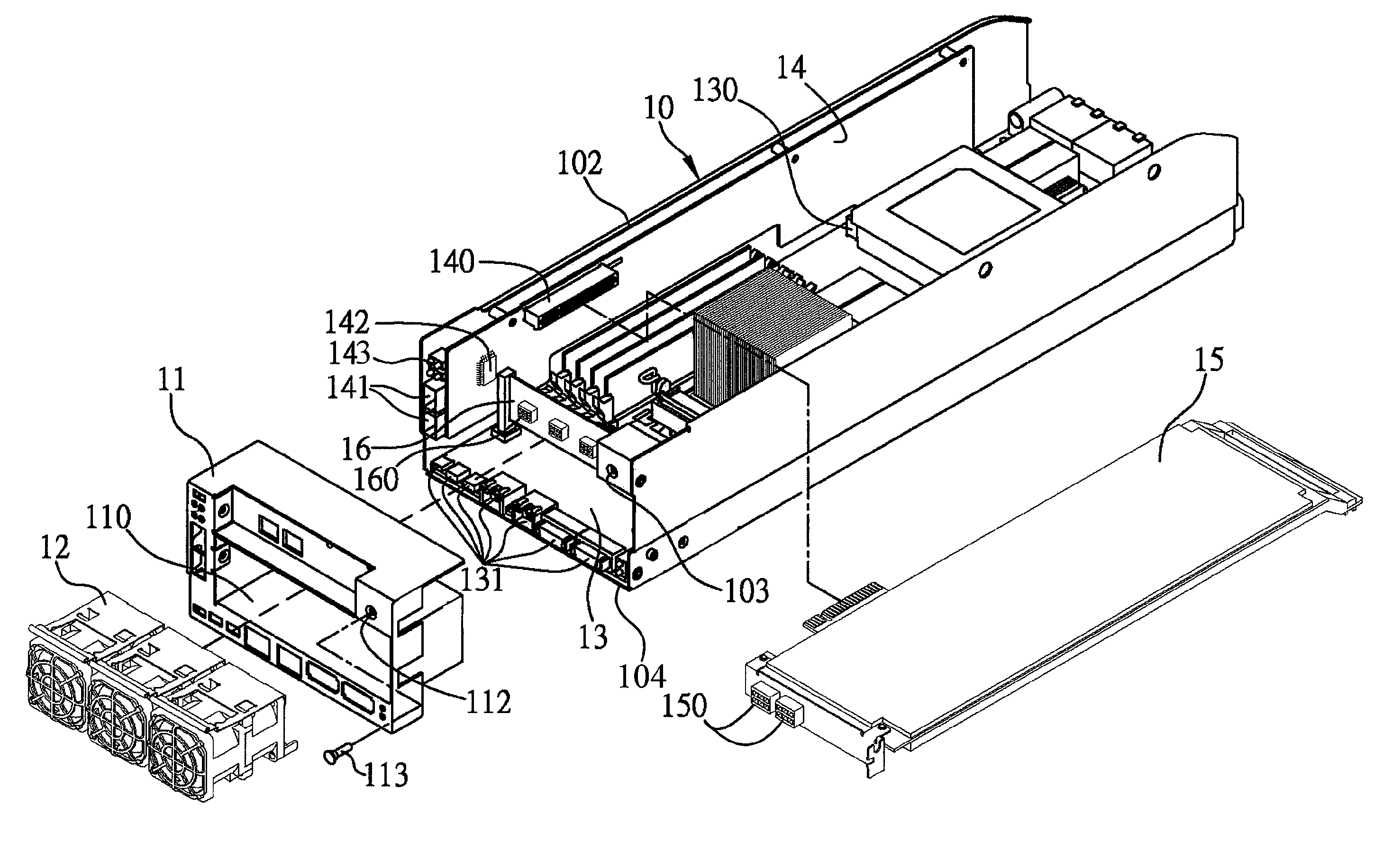
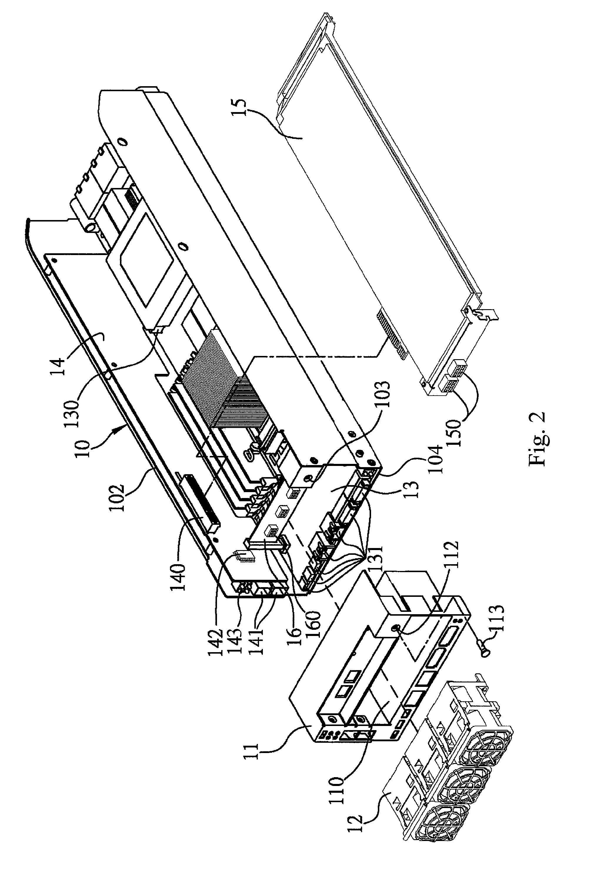
[0016]FIG. 2 illustrates an exploded view of a computer system according to one embodiment of this invention. FIG. 3 illustrates a cross-sectional view of the computer system in FIG. 2, and FIG. 4 illustrates an enlarged view of a side housing in FIG. 2.

[0017]Please refer to FIGS. 2-4. The computer system includes a main housing 10 and a side housing 11. The side housing 11 is assembled to the front of the main housing 10 as a frame so as to form a unitary housing. The side housing 11 is fastened to the main housing 10 by a bolt 113 being screwed through a hole 112 and into a threaded hole 103.

[0018]Several circuit boards are enclosed within the unitary housing, consisting of the main housing 10 and the side h...


PUM


Abstract

A physical configuration of a computer system is described. The motherboard has a first series of I / O ports at an edge thereof. A riser card is perpendicularly connected with the motherboard, wherein the riser card has a second series of I / O ports at an edge thereof. A housing encloses the motherboard and the riser card, wherein the housing has a plurality of openings, exposing each of the first series of I / O ports and the second series of I / O ports so as to form an L-shaped I / O port area on a flat surface thereof.

Description

BACKGROUND[0001]1. Field of Invention[0002]The present invention relates to a computer system. More particularly, the present invention relates to a physical configuration of a computer system.[0003]2. Description of Related Art[0004]Nowadays, how a space inside a computer system being used is carefully considered and no space should be idle. For instance, a housing of a standard computer server, i.e. a 1-U sever or 2-U sever, has been restricted to a specified size. When an unused space exists in its housing, efforts is taken to fill the unused space.[0005]FIG. 1 illustrates a conventional computer server. A housing 20 encloses several circuit boards and a fan module 22 inside. A motherboard 21 is fastened to a bottom wall of the housing. A riser card 23 is installed on the motherboard 21. Two expansion cards 24 are further installed on the riser card 23. Both the motherboard 21 and the expansion cards 24 have I / O ports. Due to the physical configuration inside the housing 20, the ...

Claims


Application Information

Patent Timeline
Patent Type & Authority Patents(United States)
IPC IPC(8): G06F1/16
CPCG06F1/186
Inventor CHEN, KUN-FU
Owner INVENTEC CORP
Why Eureka
Try Eureka