System and method for monitoring and controlling remote devices

a remote device and system technology, applied in the field of remote system monitoring, control and reporting, can solve the problems of prohibitive control system cost, inability to monitor and control such systems, etc., to achieve the effect of easy integration, easy integration, and easy mapping into the packet protocol

Inactive Publication Date: 2005-07-05
SIPCO
View PDF10 Cites 525 Cited by
  • Summary
  • Abstract
  • Description
  • Claims
  • Application Information

AI Technical Summary

Benefits of technology

[0011]To successfully communicate between the transceiver(s) and the gateway interface, the present invention receives a plurality of RF signal transmissions containing a packet protocol via RF signals that includes sender and receiver identifiers, a description of the packet itself, a message number, any commands, the data, and an error detector. In addition, the packet protocol can be easily integrated with a...

Problems solved by technology

A problem with expanding the use of control system technology is the cost of the sensor/actuator infrastructure required to monitor and control such systems.
Another prohibitive cost of control systems is the installation and operational expenses associated...

Method used


Image

  • System and method for monitoring and controlling remote devices
  • System and method for monitoring and controlling remote devices
  • System and method for monitoring and controlling remote devices

Examples


Embodiment Construction

[0023]Having summarized the invention above, reference is now made in detail to the description of the invention as illustrated in the drawings. While the invention will be described in connection with these drawings, there is no intent to limit it to the embodiment or embodiments disclosed therein. On the contrary, the intent is to cover all alternatives, modifications and equivalents included within the spirit and scope of the invention as defined by the appended claims.

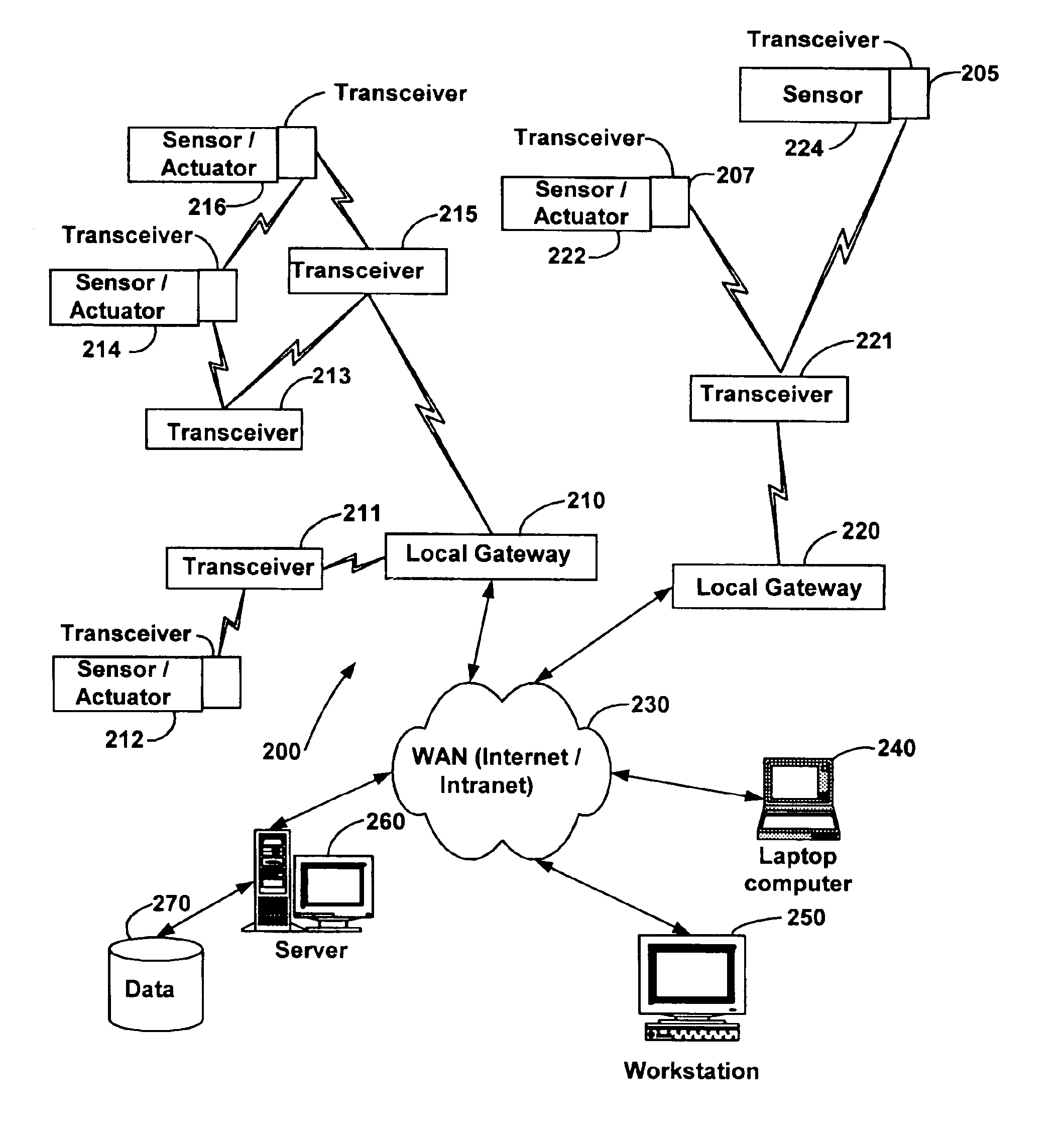
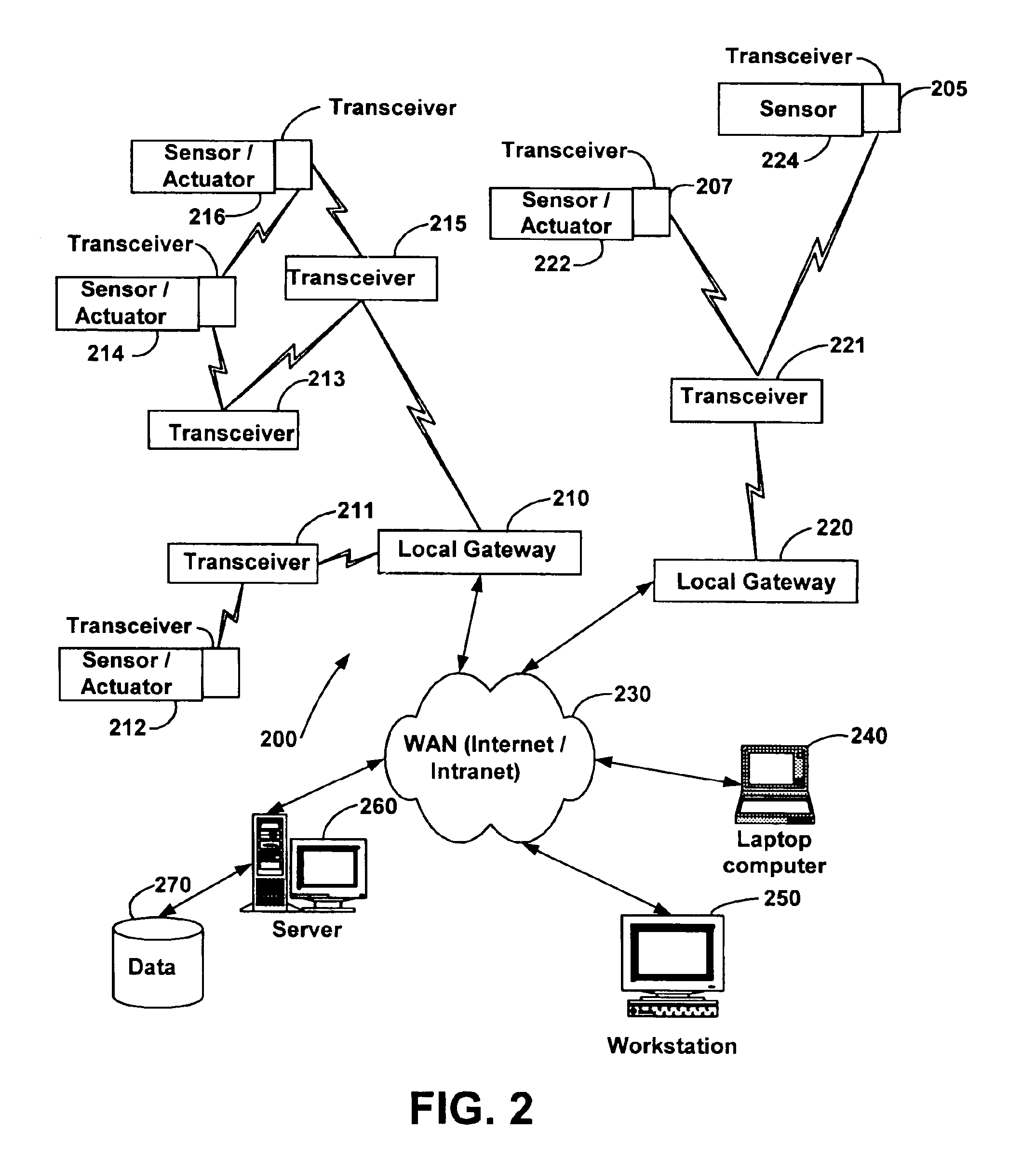
[0024]FIG. 2 sets forth a block diagram that illustrates an embodiment of a control system in accordance with the present invention. The control system 200 may consist of one or more transceivers. An exemplary transceiver 205 can be integrated with a sensor 224 to form a first combination. A second transceiver 207 can be integrated with an actuator 222 to form a second combination. The transceivers 205, 207 may preferably be wireless RF transceivers that are relatively small in size and transmit a relatively low po...


PUM


Abstract

The present system is directed to a computerized system for monitoring and controlling remote devices by transmitting data between the remote systems and a gateway interface via a packet message protocol system. The system comprises one or more remote sensors to be read and possibly one or more actuators to be remotely controlled. The remote sensor(s)/actuator(s) then interface with uniquely identified remote transceivers that transmit and/or receive data. If necessary in individual applications, signal repeaters may relay information between the transceiver(s) and the gateway interface. Communication links between the remote transceivers and the gateway interface are preferably wireless but may also be implemented via a mixture of wireless and wired communication links. To successfully communicate between the transceiver(s) and the gateway interface, the present invention receives a plurality of RF signal transmissions containing a packet protocol via RF signals that includes sender and receiver identifiers, a description of the packet itself, a message number, any commands, the data, and an error detector. In addition, the packet protocol can be easily integrated with alternate data communication protocols for use with systems other than the Internet.

Description

CROSS-REFERENCE TO RELATED APPLICATIONS[0001]This application is a continuation-in-part of U.S. patent application Ser. No. 09 / 704,150, filed Nov. 1, 2000, and entitled “System and Method for Monitoring and Controlling Residential Devices”; U.S. patent application Ser. No. 09 / 271,517; filed Mar. 18, 1999, and entitled, “System For Monitoring Conditions in a Residential Living Community;” Ser. No. 09 / 439,059, filed Nov. 12, 1999, and entitled, “System and Method for Monitoring and Controlling Remote Devices,” and Ser. No. 09 / 102,178; filed Jun. 22, 1998, entitled, “Multi-Function General Purpose Transceiver;” Ser. No. 09 / 172,554; filed Oct. 14, 1998, entitled, “System for Monitoring the Light Level Around an ATM;” Ser. No. 09 / 412,895; filed Oct. 5, 1999, entitled, “System and Method for Monitoring the Light Level Around an ATM.” Each of the identified U.S. patent applications is incorporated herein by reference in its entirety. This application also claims the benefit of U.S. provisi...

Claims


Application Information

Patent Timeline
IPC IPC(8): G01V1/36G01V1/28G08B25/00G05B1/00G05B23/02G05D1/00H04B7/00H04J3/16H04J3/22H04J3/24H04L12/28H04L12/56H04L29/08
CPCG01V1/364G05B19/4183H04L67/125G08B25/007G08B25/009G05B2219/31093Y04S40/18H04W4/14Y02P90/02G08B21/18G08B27/005H04B7/15
Inventor PETITE, THOMAS D.
Owner SIPCO
Why Eureka
Try Eureka