Wall-ceiling slip joint permitting seismic induced movement

a technology of slip joints and wall ceilings, applied in the direction of parkings, walls, shock-proofing, etc., can solve the problems of affecting the stability of the wall system, the seal between the suspending ceiling and the wall panel is susceptible to sound and/or light transference, and the wall system is not designed to be load-bearing

Active Publication Date: 2009-12-01
KRUEGER INT INC
View PDF15 Cites 30 Cited by
  • Summary
  • Abstract
  • Description
  • Claims
  • Application Information

AI Technical Summary

Problems solved by technology

The wall systems are not designed to be load bearing.
This can be particularly problematic for wall panels that are attached, using fasteners or similar connectors, directly to the suspended ceiling.
While having an improved response to seismic events, the seal between the suspending ceiling and the wall panel can be susceptible to sound and / or light transference.
This has led to the need for a series of braces above the ceiling (called kicker braces) that support the walls that can be expensive and time consuming to install.
This penetration can be wider than the width of the wall, which can compromise the effectiveness of the wall system.

Method used


Image

  • Wall-ceiling slip joint permitting seismic induced movement
  • Wall-ceiling slip joint permitting seismic induced movement
  • Wall-ceiling slip joint permitting seismic induced movement

Examples


Embodiment Construction

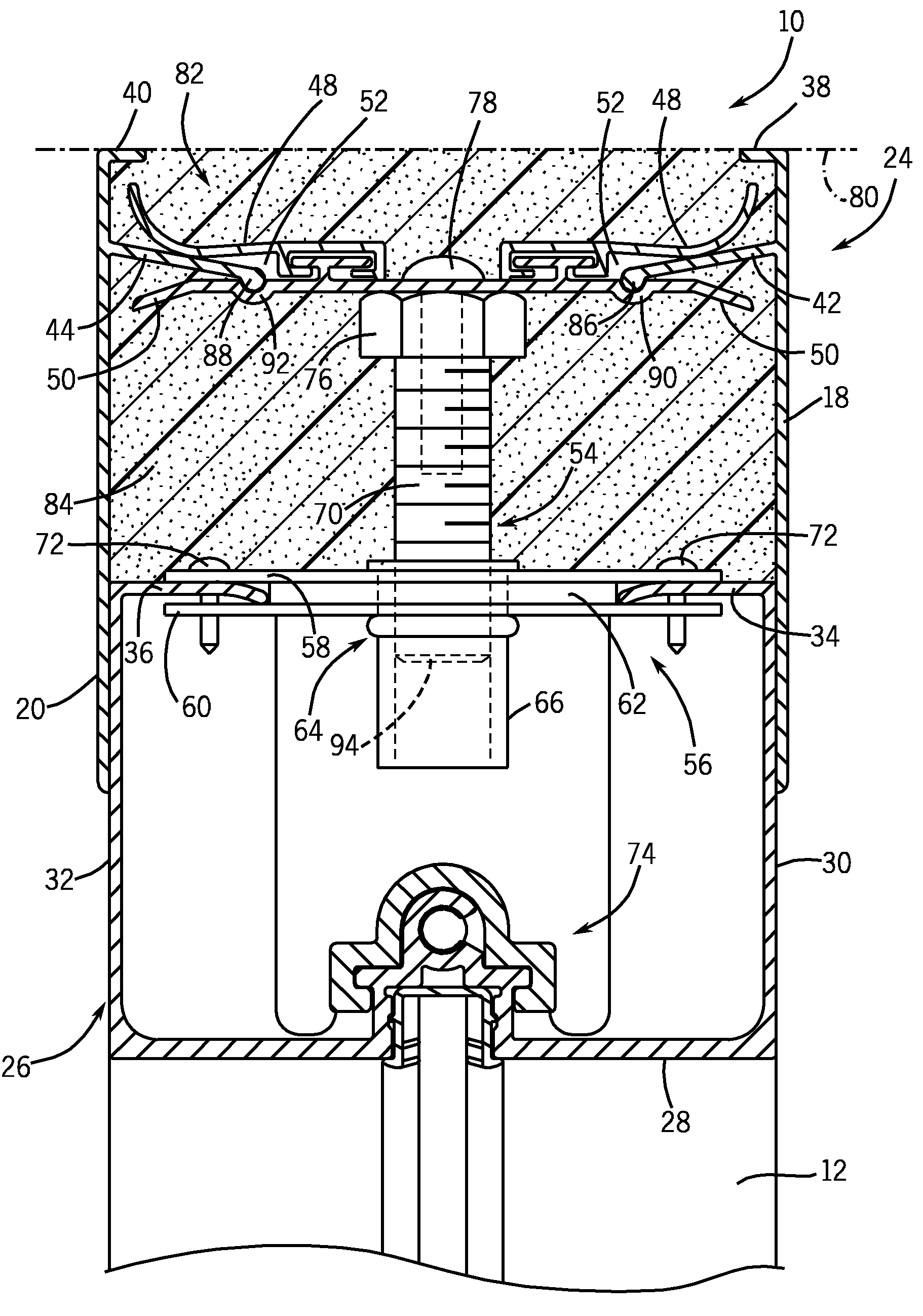
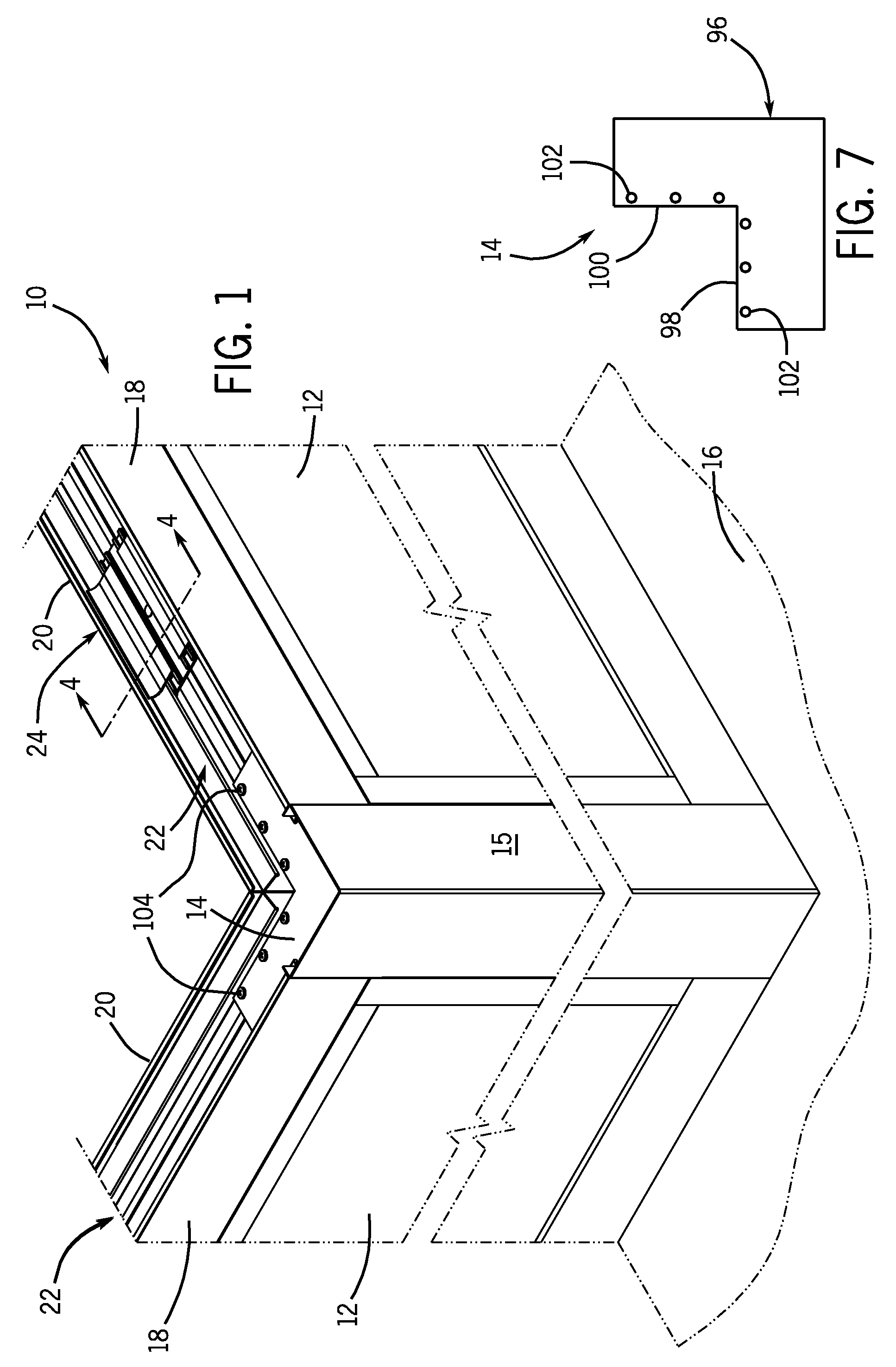
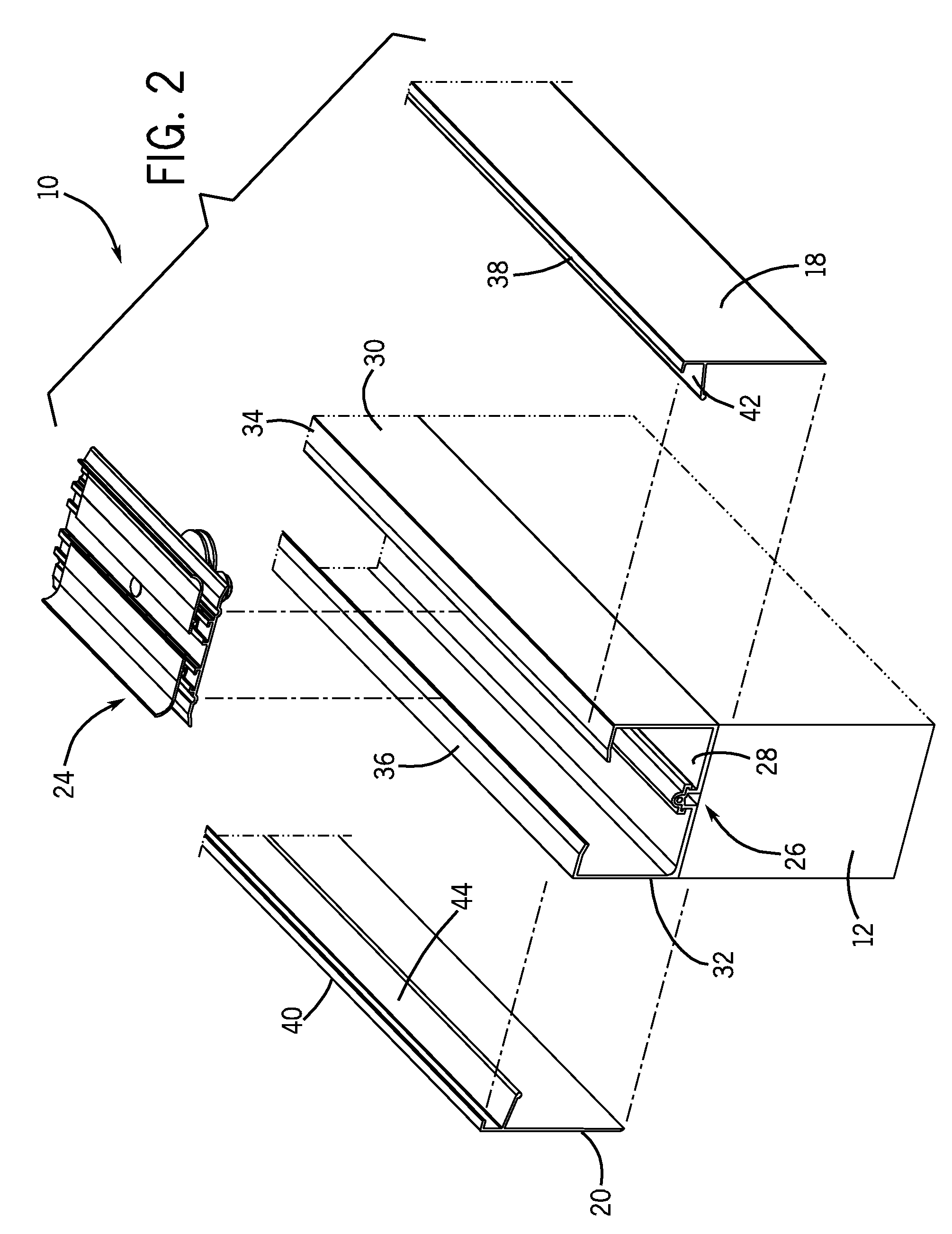
[0019]FIG. 1 shows a portion of a modular wall system 10 composed of a pair of wall panels (or partition walls) 12 connected to one another by a corner brace 14. A corner cover 15 extends from the corner brace 14 and runs the height of the pair of wall panels 12 and assists in connecting the adjacent wall panels 12 to one another. As will be described with respect to FIG. 7, the corner brace 14 allows the joined wall panels to swing as a single structure during seismic events. The wall panels 12 are designed to abut the underside of a suspended ceiling (not shown) via a slip joint connection, which will be explained. As will also be explained in greater detail below, the wall panels 12 are constructed to be shorter than the distance between the suspended ceiling and a floor, shown at 16. The gap between each wall panel 12 and the ceiling is traversed by a pair of wall extensions 18, 20 designed to abut against the underside of the suspended ceiling and be retained thereagainst witho...


PUM


Abstract

A wall panel-ceiling engagement device is designed to couple a wall panel to a ceiling. The engagement device, when engaged with the ceiling, holds the wall panel stationary without any fasteners, braces or other securing members that penetrate into the ceiling. The engagement device includes a pair of wall extensions secured to opposite sides of the wall panel and that contain a sound and / or attenuating material, such as a foam material, therebetween. Corner braces are used to join adjacent wall-panels to one another. The corner braces also function to allow the wall panels to sway as a collective and connected unit during seismic events.

Description

BACKGROUND OF THE INVENTION[0001]This invention pertains to partition wall systems and, more particularly, to an engagement assembly that couples a wall panel to the ceiling without piercing the ceiling itself. The engagement assembly may also provide a sound and light attenuation barrier. The present invention is believed to be particularly applicable for wall systems located in areas prone to measurable seismic events.[0002]Increasingly, interconnected modular wall systems are being used to define offices, conference rooms, storage rooms, and workrooms. The wall systems are not designed to be load bearing. As such, they can be fastened to the floor and the suspended ceiling of a building at nearly any location. As the needs for the office space change, such as with a new tenant, the wall systems can be rearranged or replaced, as needed, without affecting the structural integrity of the building. An exemplary modular wall system is the Genius wall system, commercially available fro...

Claims


Application Information

Patent Timeline
Patent Type & Authority Patents(United States)
IPC IPC(8): E04H1/00E04H14/00E04H3/00E04H5/00E04H6/00
CPCE04B2/82E04B2/7409
Inventor KOPISH, ANDREW J.
Owner KRUEGER INT INC
Why Eureka
Try Eureka