Concave phased array imaging catheter

Active Publication Date: 2009-12-01
SCI MED LIFE SYST
View PDF20 Cites 40 Cited by
  • Summary
  • Abstract
  • Description
  • Claims
  • Application Information

AI Technical Summary

Problems solved by technology

This will cause the beams of the individual elements, A and B, to have different amplitudes, which can undesirably result in a widened beam 20, even if an accurate time delay compensation is used.

Method used


Image

  • Concave phased array imaging catheter
  • Concave phased array imaging catheter
  • Concave phased array imaging catheter

Examples


Embodiment Construction

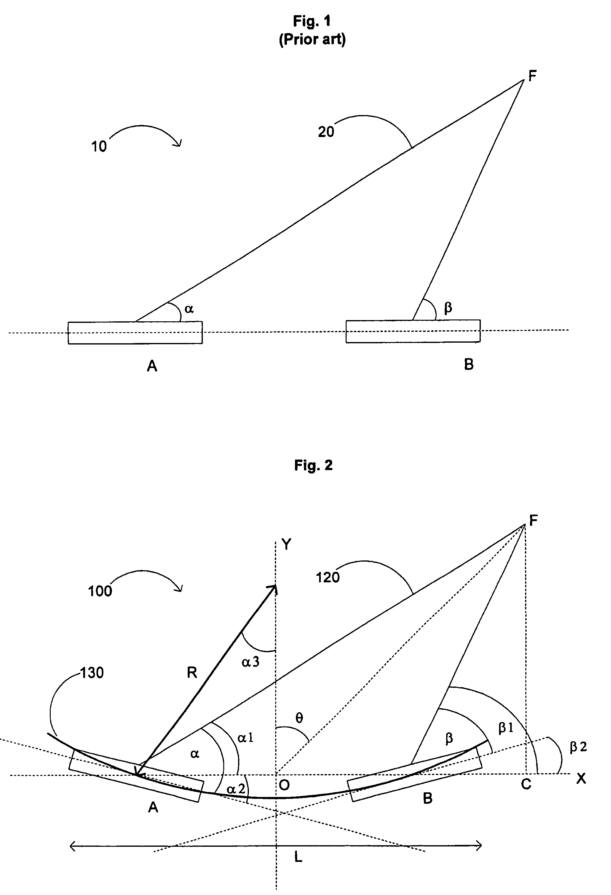
[0014]As described above, prior art phased array assemblies 10 consist of a series of small rectangular elements, A and B, that are evenly spaced in a flat plane. This configuration causes the elements to emit energy beams at different angles when the phased array beam 20 is steered and focused. This can undesirably cause a widened phased array beam 20.

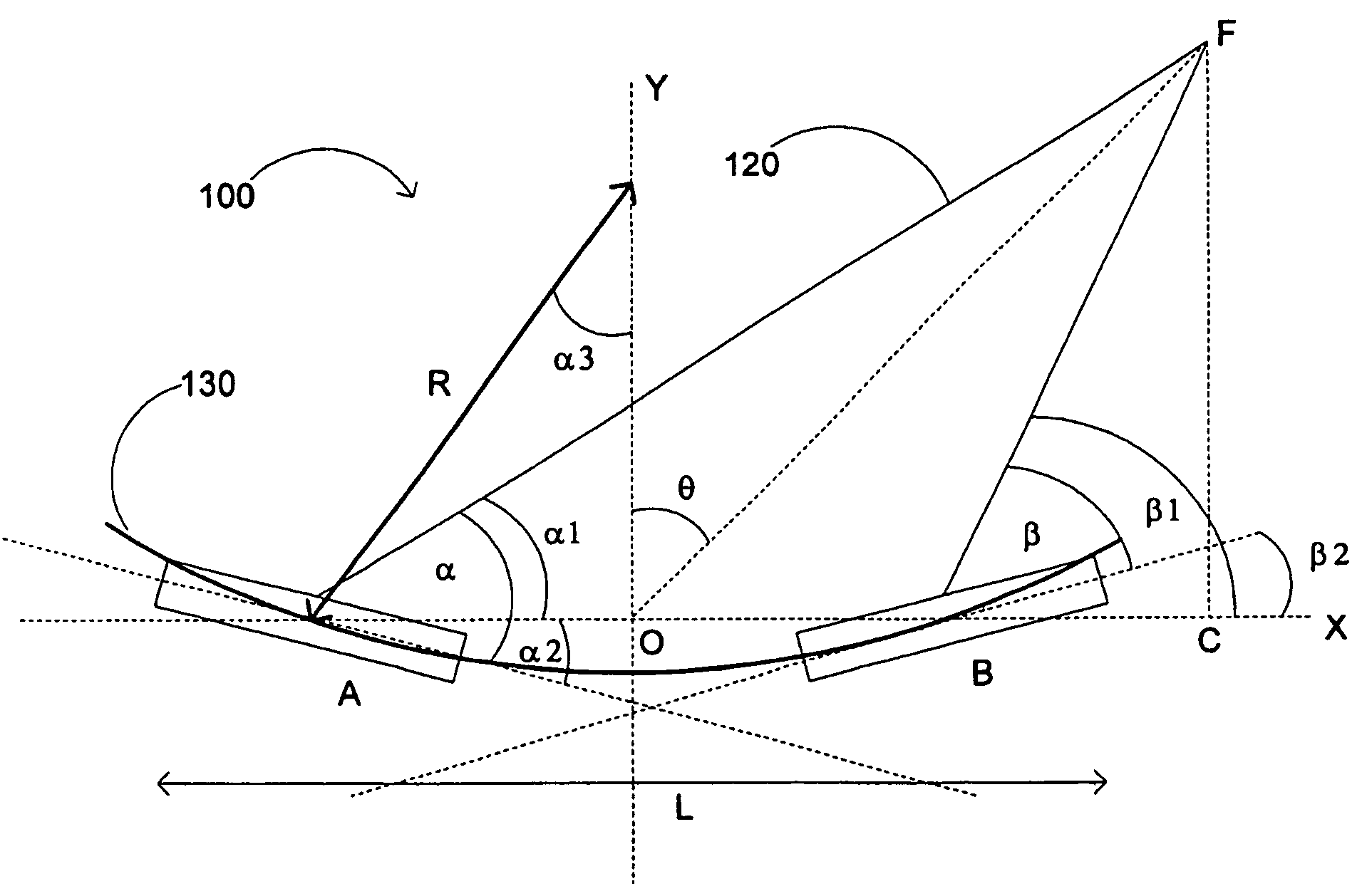
[0015]By contrast, the improved phased array in this patent specification reduces the undesired wideness by placing a phased array in a concaved configuration, as shown in FIG. 2. FIG. 2 shows a phased array 100 of imaging elements, A and B. The elements, A and B, are situated along a concave 130 path having a radius R. The phased array 100 can have additional imaging elements along the concave path 130 (not shown). The phased array 100 has a length, L, and a maximum steering angle in the azimuthal direction, θ. F represents a focal point at the maximum steering angle in the azimuthal direction. The phased array 100 is shown focusing ...


PUM


Abstract

The present invention generally relates to medical devices, and more particularly to an improved intravascular device. In one embodiment, an intravascular device includes a catheter having proximal and distal portions, and a phased array of imaging elements, having edge elements each having angles of emission, located in the distal portion of the catheter, wherein the phased array is concaved having a radius of curvature such that when the phased array is steered in a maximal azimuthal direction, the angles of emission of the edge elements are substantially similar.

Description

FIELD OF THE INVENTION[0001]The field of the invention relates to medical devices, and more particularly to phased array imaging catheters.BACKGROUND OF THE INVENTION[0002]Intraluminal, intracavity, intravascular, and intracardiac treatments and diagnosis of medical conditions utilizing minimally invasive procedures are effective tools in many areas of medical practice. These procedures are typically performed using imaging and treatment catheters that are inserted percutaneously into the body and into an accessible vessel of the vascular system at a site remote from the vessel or organ to be diagnosed and / or treated, such as the femoral artery. The catheter is then advanced through the vessels of the vascular system to the region of the body to be treated. The catheter may be equipped with an imaging device, typically an ultrasound imaging device, which is used to locate and diagnose a diseased portion of the body, such as a stenosed region of an artery. For example, U.S. Pat. No. ...

Claims


Application Information

Patent Timeline
Patent Type & Authority Patents(United States)
IPC IPC(8): A61B8/14
CPCA61B8/12B06B1/0633A61B8/4488
Inventor CAO, PEI JEIYUAN, JIAN R.TIERNEY, MICHAEL J.
Owner SCI MED LIFE SYST
Why Eureka
Try Eureka