Method and apparatus for magnetically controlling motion direction of a mechanically pushed catheter

a technology of magnetic control and motion direction, which is applied in the direction of catheters, applications, diagnostic recording/measuring, etc., can solve the problems of less suitable arrangement for moving implants, difficulty in finding a set of currents to accomplish a move step, and inability to find undesired magnetic forces on implants, etc., to achieve reliable, predictable strength, and control the motion of catheters quickly, accurately and reliably

Inactive Publication Date: 2009-12-01
STEREOTAXIS
View PDF11 Cites 22 Cited by
  • Summary
  • Abstract
  • Description
  • Claims
  • Application Information

AI Technical Summary

Benefits of technology

[0031]It is a further object of the invention to control the motion of a catheter by applying a torque to the catheter to guide its direction with a reliable, predictable strength.
[0032]It is yet another object of the invention to c

Problems solved by technology

However, difficulty in finding a set of currents to accomplish a move step is encountered because of the complexity of calculating the magnetic forces resulting from multiple coils.
Because the field is quite uniform near the midpoint, undesired magnetic forces on the implant are negligible.
However, this arrangement is less suitable for a moving implant when the implant is some distance from the midpoint between the coils or not on the axis, or when the implant axis is, not along the coil axis.
In these important cases, this simple coil arrangement cannot provide accurate directional guidance.
Furthermore, simple vector combinations of three such coil pair arrangements cannot provide accurate guidance in an arbitrary direction, except at one spot at the center of the arrangement.
The conventional problem of electro

Method used


Image

  • Method and apparatus for magnetically controlling motion direction of a mechanically pushed catheter
  • Method and apparatus for magnetically controlling motion direction of a mechanically pushed catheter
  • Method and apparatus for magnetically controlling motion direction of a mechanically pushed catheter

Examples


Embodiment Construction

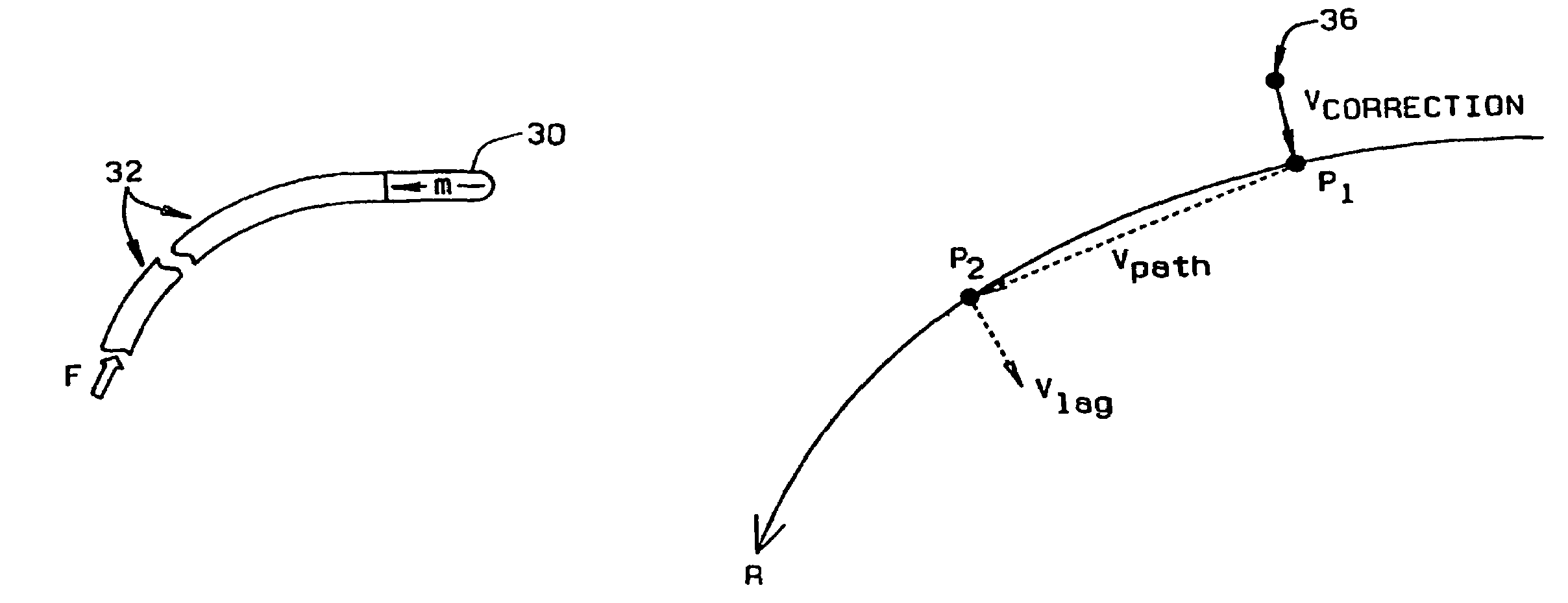
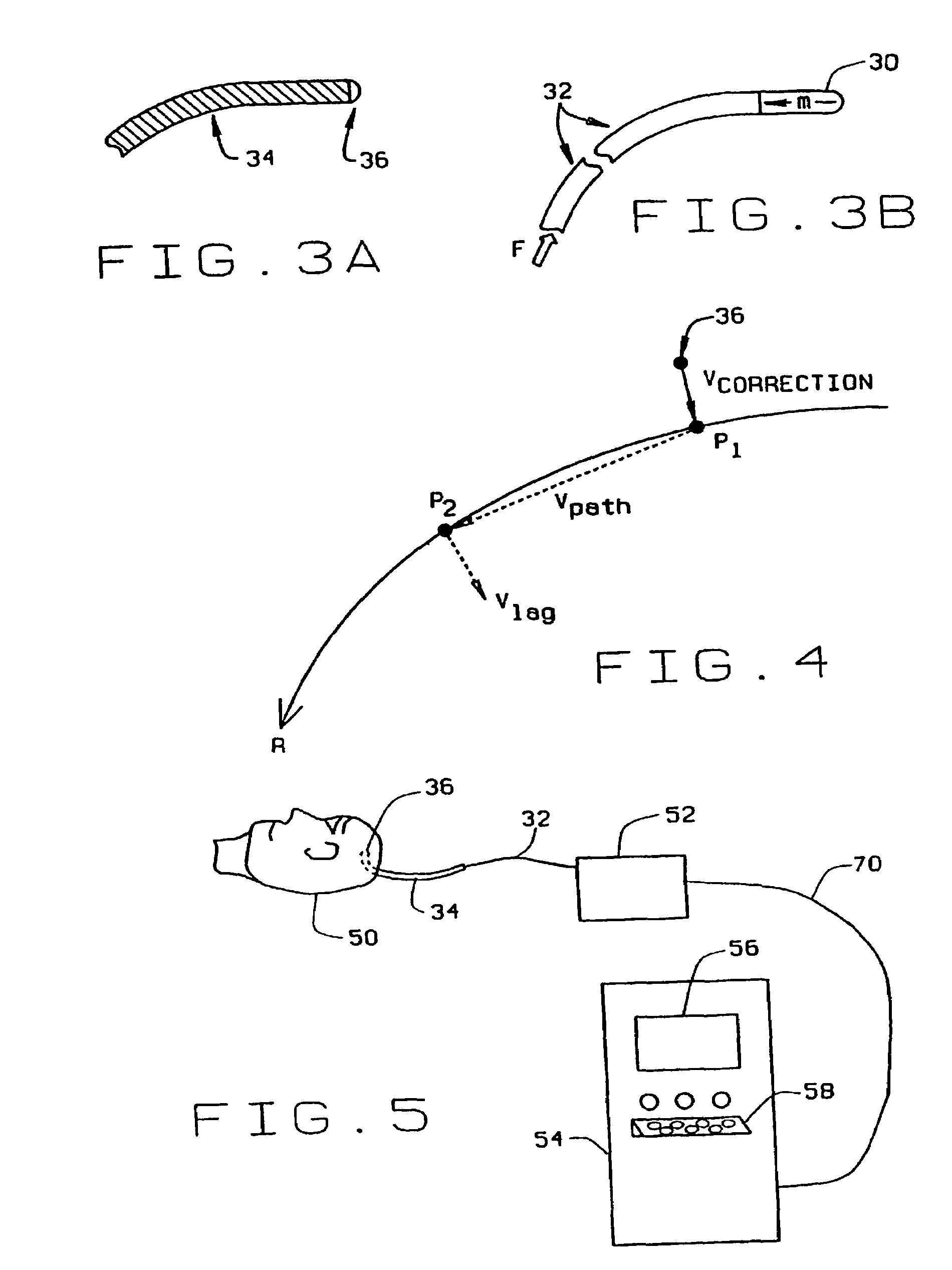
[0040]The invention is described herein in the context of guiding an implant inside a brain because tests have been performed for this case. However, those skilled in the art will recognize that the invention is applicable to other parts of the body and to other media through which a magnetic tip at the end of a flexible catheter can be pushed.

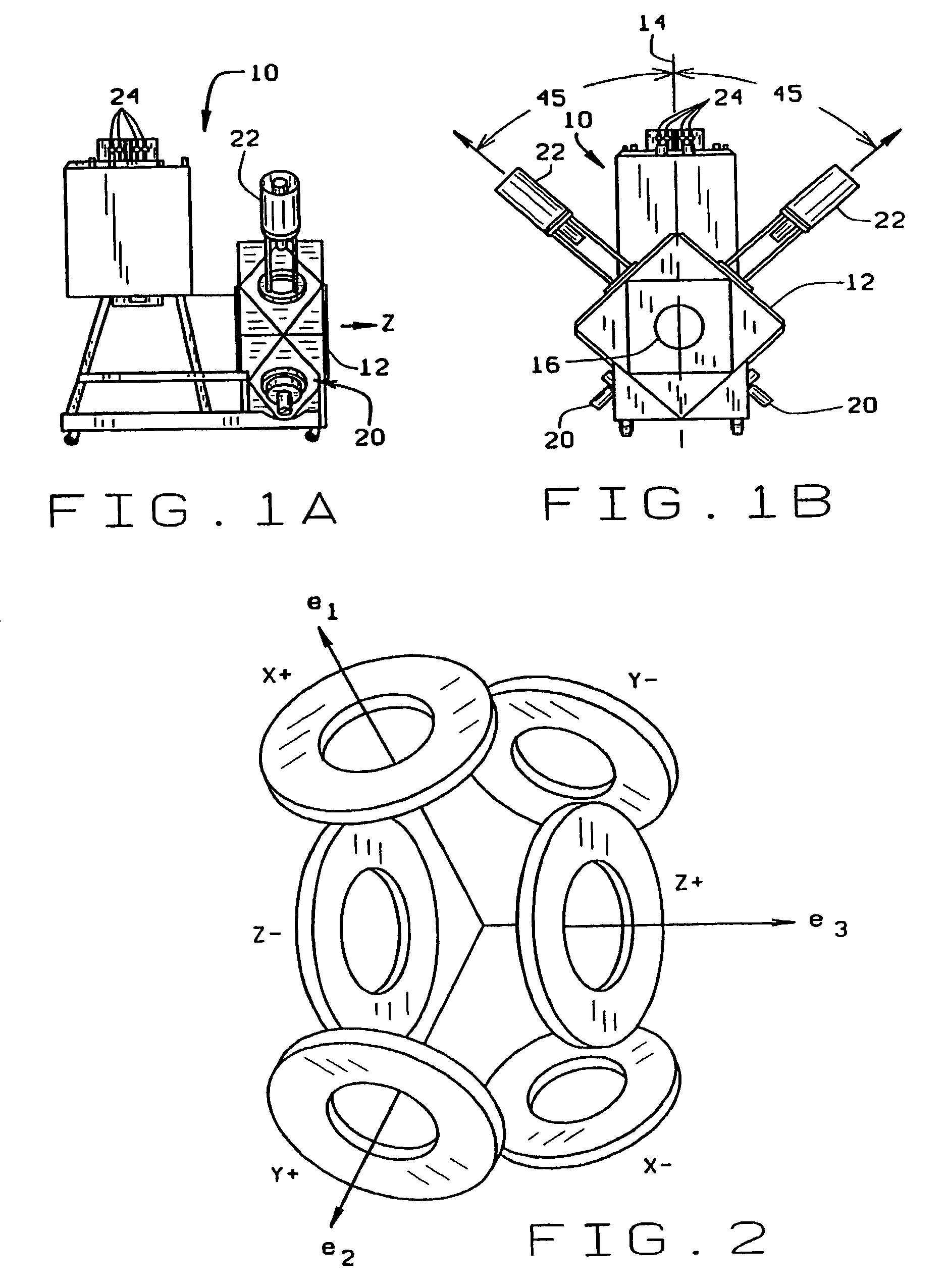
[0041]In the present example, a system of six coils is provided. Referring to FIG. 2, which is a simplified representation of the coil geometry, the coils X+, X−, Y+, Y−, Z+, and Z− are operated in unbalanced pairs (X+, X−), (Y+, Y−), (Z+, Z−) acting approximately as three vectors X, Y, and Z having mutually perpendicular directions, but different magnitudes. The operation is achieved in a manner that is effective at positions off the axis of any or all of the three pairs of coils (X+, X−), (Y+, Y−), (Z+, Z−) constituting the helmet (or other coil support arrangement).

[0042]The method for controlling the path in the Magnetic Stereotaxis System...


PUM


Abstract

The movement of a catheter through a medium, which may be living tissue such as a human brain, is controlled by mechanically pushing a flexible catheter having a magnetic tip through the medium and applying a magnetic field having a magnitude and a direction that guides the mechanically-pushed catheter tip stepwise along a desired path. The magnetic field is controlled in a Magnetic Stereotaxis System by a processor using an adaptation of a PID (proportional, integral, and derivative) feedback method. The magnetic fields are applied by superconducting coils, and the currents applied through the coils are selected to minimize a current metric.

Description

CROSS-REFERENCE TO RELATED APPLICATIONS[0001]This application is a continuation of U.S. patent application Ser. No. 09 / 357,203 filed on Jul. 20, 1999, now U.S. Pat. No. 6,475,223, which was a divisional of U.S. patent application Ser. No. 08 / 920,446 filed on Aug. 29, 1997, now U.S. Pat. No. 6,015,414. The disclosures of the above applications are incorporated herein by reference.BACKGROUND OF THE INVENTION[0002]1. Field of the Invention[0003]This invention relates to devices and methods for moving an implant in a body, and more particularly to such devices and methods that apply pushing forces with a flexible attachment and that magnetically steer the implant in the body with high accuracy.[0004]2. Description of Related Art[0005]There is a large body of conventional (nonmagnetic) stereotactic prior art, in which a frame (e.g., a so-called “BRW Frame”) is attached to the skull to provide a navigation framework. Such a frame has arcs to determine an angle of an “insertion guide” whic...

Claims


Application Information

Patent Timeline
IPC IPC(8): A61F11/00A61B5/06A61B6/12A61B19/00A61M25/00A61M25/01A61M25/095
CPCA61B19/20A61M25/0127A61M25/01A61B6/12A61B2019/2253A61B2019/5236A61B2019/2261A61B90/10A61B34/73A61B2034/732A61B2090/374
Inventor WERP, PETER R.BLUME, WALTER M.CREIGHTON, IV, FRANCIS M.RITTER, ROGERS C.
Owner STEREOTAXIS
Why Eureka
Try Eureka