Energy converter, flag type energy converter

a flag type, energy converter technology, applied in the direction of generator/motor, machine/engine, generator control, etc., to achieve the effect of low cost, low damage risk, and low probability of human beings being fatally injured

Inactive Publication Date: 2009-12-01
KYOTO UNIV
View PDF36 Cites 66 Cited by
  • Summary
  • Abstract
  • Description
  • Claims
  • Application Information

AI Technical Summary

Benefits of technology

[0019]With the above-described constitution, because the flexible plane unit it self has no proper period, it flutters by the pulse of the fluid flow while changing its shape according to the ever-changing pressure distribution of the fluid, and the vibration on the flexible plane unit is excited at any flow velocity by absorbing the energy such as a pressure of the fluid. And, the vibration excited on the flexible plane unit is transmitted through the transmission unit to the energy conversion unit to be converted into electric energy. Moreover, because the flexible plane unit, which is a portion for receiving the fluid flow, is not rigid like the funs of the propeller type pinwheel, there is little fear for the damage by the fluid turbulence. Even if such a damage happens by any chance, the probability of the fatal injure to human beings is greatly low. And, this system can be realized at low cost, because the flexible plane unit is made of a cloth.
[0020]That is to say, it is allowable to provide the energy converter that is able to generate electricity without depending on a velocity of fluid, is safe to have little fear of damage with fluid such as the turbulent wind and is able to be realized economically.

Problems solved by technology

In recent years, environmental problems such as the global warming have increased the expectation to the energy converter that generates an electric power by using wind that is a natural energy.

Method used


Image

  • Energy converter, flag type energy converter
  • Energy converter, flag type energy converter
  • Energy converter, flag type energy converter

Examples


first embodiment

[0029]The first embodiment is explained below referring to the figure.

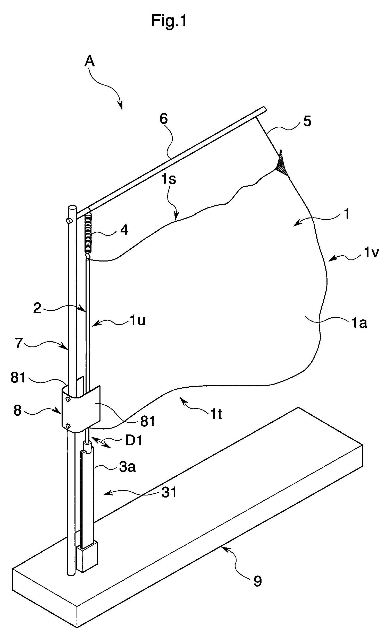
[0030]The energy converter A of this embodiment has a function of a flag type energy converter. As shown in FIG. 1, the energy converter A comprises a substantially rectangular flexible plane unit 1, a stick-like flagpole 2 attached to a windward side of the flexible plane unit 1, a bottom side piezoelectric energy conversion unit 31 connected with a bottom end portion of the flagpole 2 and converting a vibration energy into an electric energy, a rod shaped crosspiece 6 installed along a topside of a peripheral edge is of the flexible plane unit 1 to support a leeward portion of the upside peripheral edge is through a coil spring 4 and a windward portion of the upside peripheral edge is through a cord 5, a supporting pole 7 installed along the flagpole 2 and the piezoelectric energy converter 31 and supporting a windward portion of the crosspiece 6, a stopper 8 fixed at a middle position of the supporting pole 7 a...

second embodiment

[0047]Other embodiment of the present invention is explained below referring to the FIG. 2. Now, corresponding sighs are given to the units or the elements having the same function with the first embodiment, and the explanation is omitted.

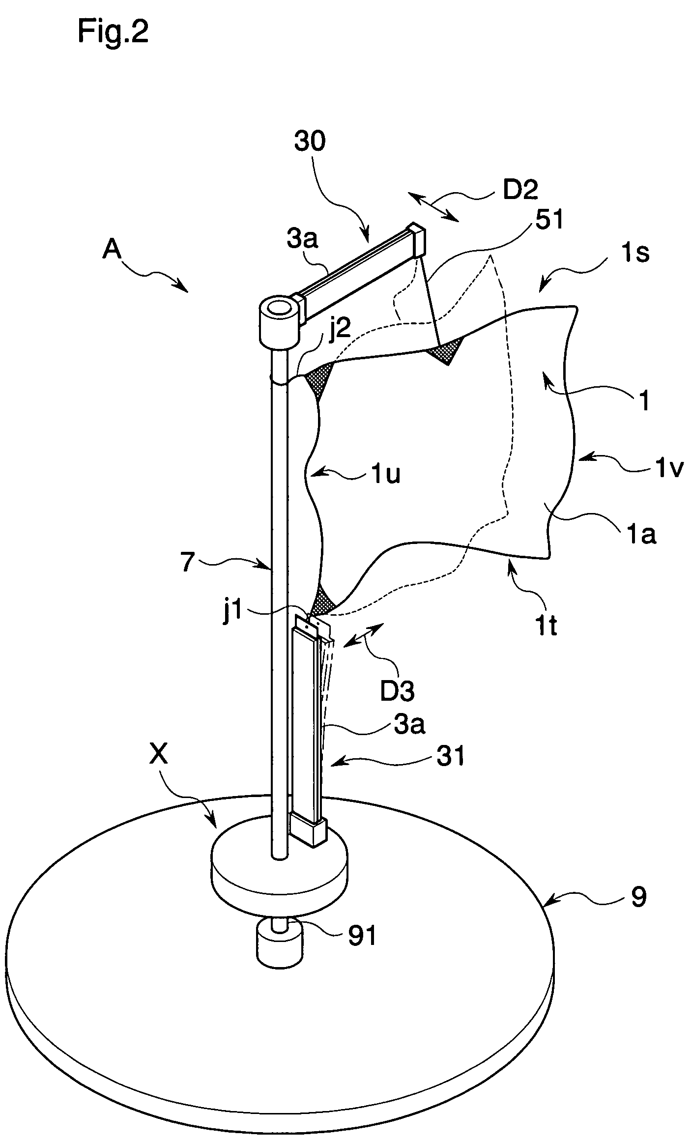
[0048]As shown in FIG. 2, the energy converter A of this embodiment comprises the flexible plane unit 1 substantially rectangular, a topside piezoelectric energy conversion unit 30 arranged along the upper side peripheral edge 1s of the flexible plane unit 1, supporting substantially middle portion of the upper side peripheral edge 1s of the flexible plane unit 1 through a cord 51 as a transmission unit and converting the vibration energy into the electric energy, the bottom side piezoelectric energy conversion unit 31 attached to the flexible plane unit 1 through a string j1 as the transmission unit and converting the vibration energy into the electric energy, the supporting pole 7 arranged along the pedestal side of the flexible plane unit 1 and ...

third embodiment

[0058]Other embodiment of the present invention is explained below referring to the FIG. 3. Now, corresponding sighs are given to the units or the elements having the same function with the first embodiment, and the explanation is omitted.

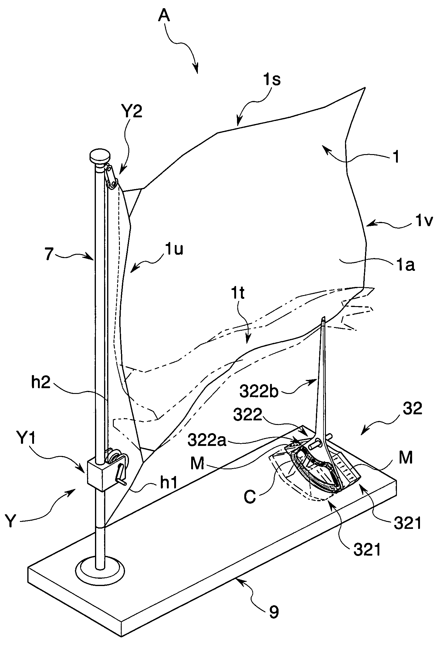
[0059]As shown in FIG. 3, the energy converter A of this embodiment comprises the substantially rectangular flexible plane unit 1, the supporting pole 7 placed along the pedestal side of the flexible plane unit 1, hanging height position changing means Y attached to the supporting pole 7 for changing the height of the flexible plane unit 1, an electromagnetic induction type energy conversion unit 32 attached to a pedestal portion of the bottom side peripheral edge it of the flexible plane unit 1 and converting the vibration energy into electric energy, a string h1 arranged between a pedestal portion of the bottom side peripheral edge 1t of the flexible plane unit 1 and the supporting pole 7, and the base structure 9 supporting the supporting pole 7...


PUM


Abstract

An energy converter comprises a flexible plane unit 1 placed in a position to be exposed to a flow of fluid such as wind, at least a part of peripheral edge of the flexible plane unit 1 being capable of fluttering freely with the flow, an energy conversion unit 31 for converting vibration energy into electric energy, and a transmission unit 2 connected to the flexible plane unit 1 and for transmitting a vibration caused on the flexible plane unit by the flow to the energy conversion unit 31.

Description

TECHNICAL FIELD[0001]The present invention relates to an energy converter or the like for extracting energy from a vibration excited on the flexible plane by a fluid.BACKGROUND[0002]In recent years, environmental problems such as the global warming have increased the expectation to the energy converter that generates an electric power by using wind that is a natural energy.[0003]This kind of energy converter, such as a propeller type impeller consisting of one or plural fans which is realized a portion to be received wind by rigid member, or a generator which is utilized a vibration exited on a cloth perpendicular, and in which a portion to be received wind is a flexible member, the cloth being extended with some tension in parallel with guide boards which are arranged so as to form a gap guiding wind, is known (for instance, refer to patent document 1).[0004]Patent document: U.S. Pat. No. 4,348,594DISCLOSURE OF INVENTIONProblems to be Solved by the Invention[0005]However, in an arr...

Claims


Application Information

Patent Timeline
Patent Type & Authority Patents(United States)
IPC IPC(8): F03B13/00F02B63/04F03D9/00F03G7/08H02K7/18
CPCF03D5/06H02K7/1892H02N2/185F05B2210/16F05B2240/311F05B2280/6001Y02E10/721Y02E10/70F05C2253/02Y02E10/72
Inventor KAWAI, HIROMASA
Owner KYOTO UNIV
Why Eureka
Try Eureka