RF-photonic transversal filter method and apparatus

a transversal filter and photonic technology, applied in the field of photonic transversal filters, can solve the problems that the slsr achieved via conventional schemes that utilize wavelength reuse is too small to be of practical interest in the above applications, and achieve the effect of large variation in passband width (f, high slsr, high slsr)

Inactive Publication Date: 2009-12-01
HRL LAB
View PDF4 Cites 18 Cited by
  • Summary
  • Abstract
  • Description
  • Claims
  • Application Information

AI Technical Summary

Benefits of technology

This patent describes an invention that allows for creating a flexible RF-photonic filter that supports changes in its bandwidth while keeping its signal quality high. This flexibility comes from generating multiple signals at different locations along the optical path, which are then combined back together through tap weight apodization. Tap weight apodization controls the amplitude of these signals to achieve specific functions like the sinc or chebyshev functions. Overall, this technology enables better performance and more versatility in design options for RF filters.

Problems solved by technology

This patent discusses the technical problem of achieving both high filter accuracy and narrow passbands in RF-photonic filters. Current methods involve reducing the number of laser sources but this results in lowered accuracy due to reduced tap numbers. There is a need for a solution that enables high accuracy without sacrificing narrow passbands and effective side lobe reduction.

Method used


Image

  • RF-photonic transversal filter method and apparatus
  • RF-photonic transversal filter method and apparatus
  • RF-photonic transversal filter method and apparatus

Examples


Embodiment Construction

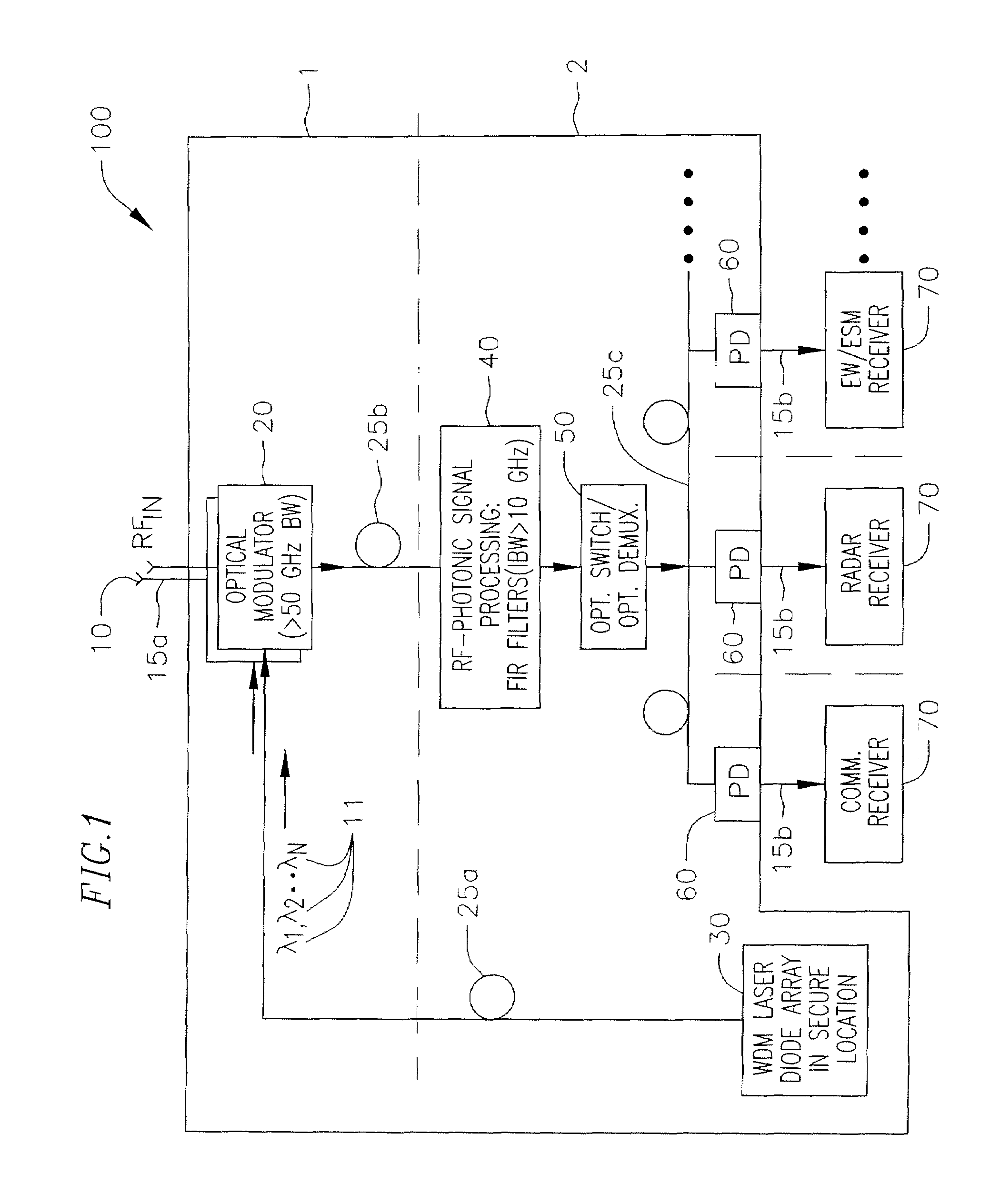
[0027]FIG. 1 shows a fiber-remoted multifunction antenna system 100 that includes RF-photonic pre-filtering of the RF transmissions received before providing them for photodetection and conversion back to RF signals. Conversion of RF input into optical signals and performing the signal processing operations and subsequent transmissions in the optical domain helps more efficient processing and transfer of the signal because transmission of optical signals is far less lossy than RF and microwave transmission. Embodiments of the invention provide an efficient and accurate photonic pre-filtering scheme that may be used in the antenna system 100.

[0028]The antenna system 100 receives RF waves at an antenna located in area 1 that is not necessarily secure. Laser sources used to form an RF-photonic filter and microwave receivers utilizing the received, filtered and processed RF waves are typically located in a secure (or benign) environment 2. RF waves arrive at a remoted antenna 10 and are...


PUM


Abstract

A method and apparatus for implementing an RF photonic transversal filter that utilizes tap apodization and wavelength reuse to obtain a high side lobe suppression together with narrow and configurable passbands. Several taps are obtained from one wavelength by using dispersive optical delay lines such as chirped fiber gratings that introduce a delay between successive wavelengths. A selected subset of the input wavelengths is utilized to generate multiple taps per wavelength. Some of the taps are apodized to generate various filter transfer functions that yield a high side lobe suppression ratio.

Description


Claims


Application Information

Patent Timeline
Owner HRL LAB
Why Eureka
Try Eureka