Cervical intervertebral prosthesis system

a technology prosthesis, which is applied in the field of cervical intervertebral prosthesis, can solve the problems of too far away

Inactive Publication Date: 2009-12-08
CERVITECH INC
View PDF46 Cites 13 Cited by
  • Summary
  • Abstract
  • Description
  • Claims
  • Application Information

AI Technical Summary

Benefits of technology

[0006]The invention also relates to a method for determining which intervertebral prosthesis from a plurality of intervertebral prostheses with different hinge radius is suitable for replacing a cervical intervertebral disk. This method is distinguished in that the hinge radius of the affected joint is determined and a prosthesis with a hinge radius approximating to this hinge radius is selected. In this context, the hinge radius 20 is to be understood as the distance between the center of the hinge movement and the midpoint of the prosthesis. The method can be implemented by the physician. However, because of the existing damage, the physician will in general no longer be able to determine the movement characteristics of the joint that is to be replaced. He will therefore rely on the manufacturer of the prostheses carrying out suitable tests, whose results can also subsequently be consulted in the literature, and on said manufacturer then assigning the available prostheses, which are put together in sets, to specific intervertebral spaces. The table below shows an example of how the radii of curvature of the slide surfaces are assigned to the individual intervertebral spaces within defined size ranges (in millimeters).
[0008]As regards the use of small radii of curvature, it should be noted that here too the hinge center lies outside the prosthesis.

Problems solved by technology

This approximates to the natural conditions but is still too far remote from them.

Method used


Image

  • Cervical intervertebral prosthesis system
  • Cervical intervertebral prosthesis system

Examples


Embodiment Construction

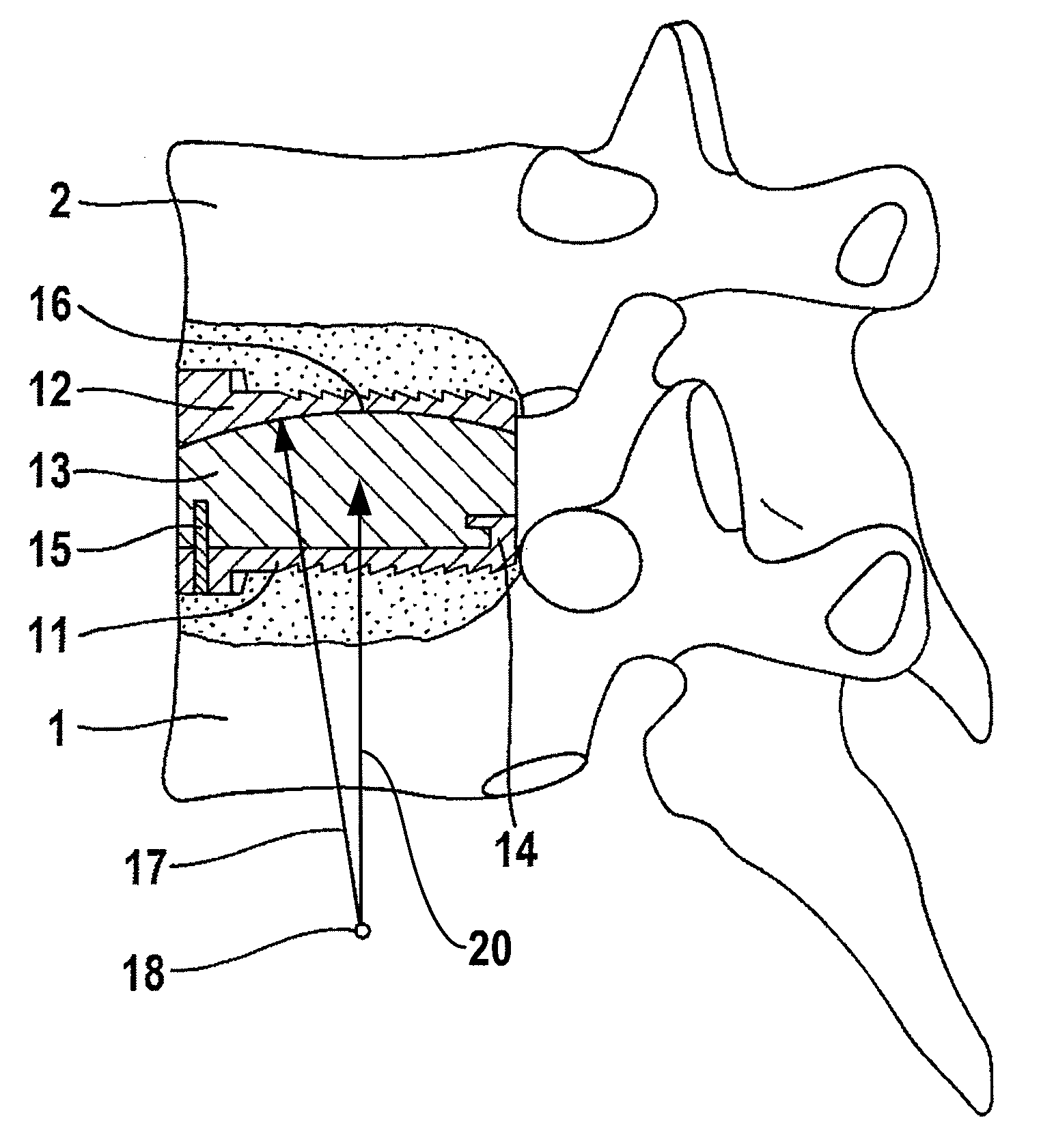
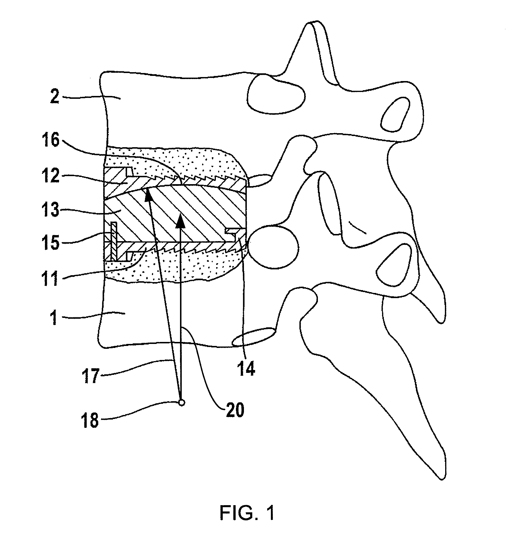
[0010]An intervertebral prosthesis made up of a lower cover plate 11, an upper cover plate 12 and a prosthetic core 13 is fitted between the vertebral bodies 1 and 2. The prosthetic core 13 is held securely on the lower cover plate 11 by an undercut ledge 14, running along three sides of the prosthesis, and by a catch 15. With the upper cover plate 12, it forms a spherical slide surface pair 16 having a slide surface radius 17 and a center of curvature 18 which forms the center of movement of the hinge formed by the prosthesis. This means that the cover plates 11, 12 and the vertebrae 1, 2 connected to them are able to execute a relative movement with respect to one another which represents a rotation movement about the center 18 as long as the slide surface pair 16 alone determines the relative movement. In practice, other slide surfaces, namely the articular facets, are also involved in determining the relative movement, so that the relative movement actually taking place may devi...


PUM


Abstract

A cervical intervertebral prosthesis system includes prostheses which each have a hinge with a predefined center of hinge movement. To permit better adaptation to the different hinge radii of the cervical intervertebral disks, the cervical intervertebral prostheses of the system include at least two prostheses with different hinge radii.

Description

FIELD AND BACKGROUND OF THE INVENTION[0001]The invention relates to cervical intervertebral prostheses which have a predefined center of the hinge movement. In a first known type of such prostheses, the center of the hinge movement is located inside the prosthesis (U.S. Pat. No. 5,425,773; EP-A-1166725) . This does not correspond to the natural conditions which the prosthesis is intended to simulate. In another type of intervertebral prosthesis (FR-A-2718635), the hinge is formed by a pair of slide surfaces, the common center of curvature of which lies outside the prosthesis, specifically under it. This approximates to the natural conditions but is still too far remote from them.SUMMARY OF THE INVENTION[0002]The invention is based on the awareness that the centers of the cervical intervertebral hinge movement are different from vertebra to vertebra (L. Penning: Functional Pathology of the Cervical Spine; Excerpta Medica 1968, pages 1-23). Starting out from this realization, the inve...

Claims


Application Information

Patent Timeline
Patent Type & Authority Patents(United States)
IPC IPC(8): A61F2/44A61F2/00A61F2/30
CPCA61F2/4425A61F2002/30327A61F2002/30383A61F2002/30387A61F2002/30517A61F2250/0039A61F2002/30616A61F2002/30649A61F2002/30904A61F2002/443A61F2220/0025A61F2002/30576
Inventor LINK, HELMUT D.
Owner CERVITECH INC
Why Eureka
Try Eureka