Panic exit door lock allowing locking on both sides

a technology for exit doors and panic exits, applied in the field of panic exit door locks, can solve the problems that the deadlocking function of conventional locks cannot be set or removed from the inner side of the panic exit door, and achieve the effect of preventing the loss of li

Active Publication Date: 2009-12-22
I TEK METAL MFG
View PDF26 Cites 17 Cited by
  • Summary
  • Abstract
  • Description
  • Claims
  • Application Information

AI Technical Summary

Benefits of technology

[0025]All figures are drawn for ease of explanation of the basic teachings of the present invention only; the extensions of the figures with respect to number, position, relationship, and dimensions of the parts to form the preferred embodiments will be explained or will be within the skill of the art after the following teachings of the present invention have been read and understood. Further, the exact dimensions and dimensional proportions to conform to specific force, weight, strength, and similar requirements will likewise be within the skill of the art after the following teachings of the present invention have be...

Problems solved by technology

However, the deadlocking function of the conventional locks c...

Method used


Image

  • Panic exit door lock allowing locking on both sides
  • Panic exit door lock allowing locking on both sides
  • Panic exit door lock allowing locking on both sides

Examples


Embodiment Construction

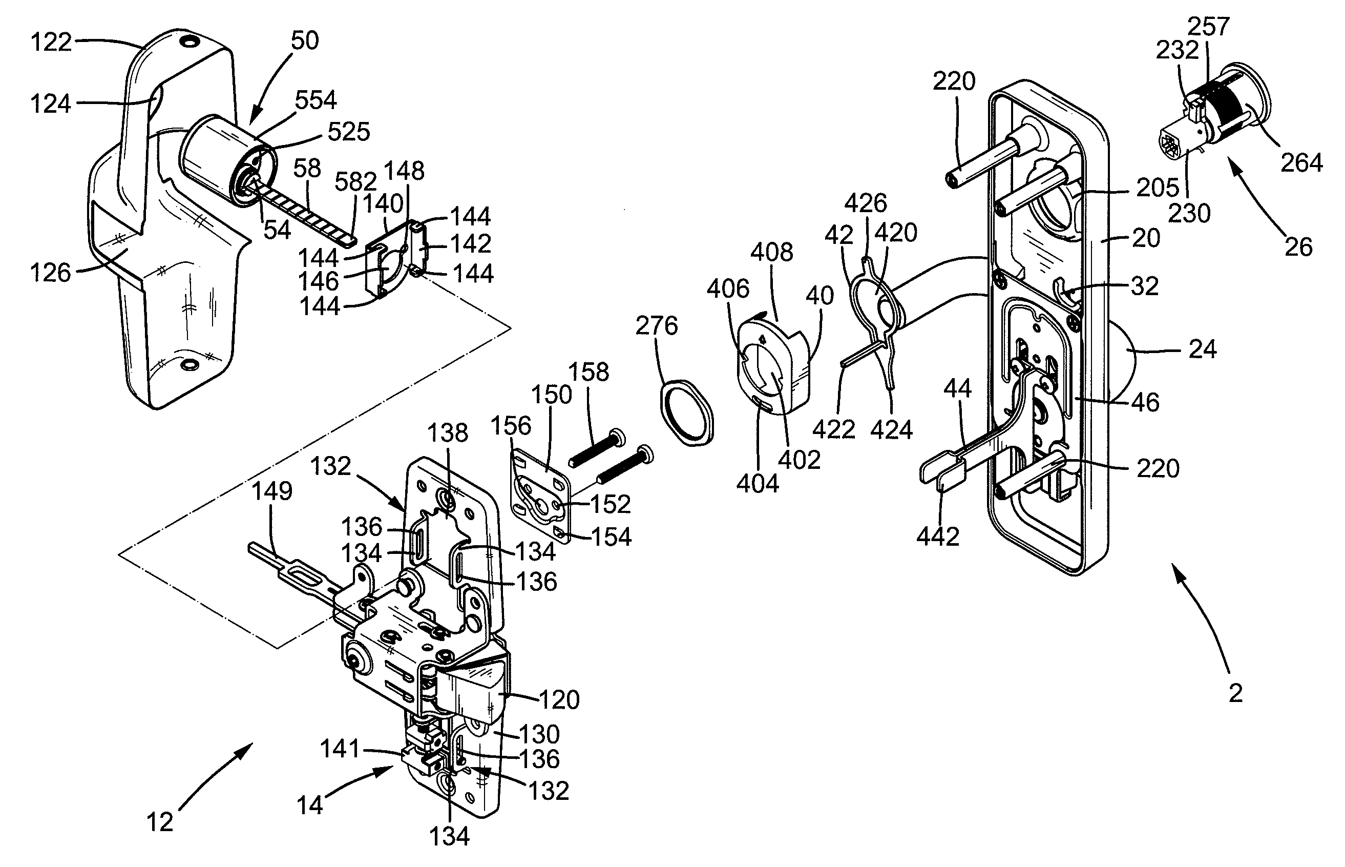
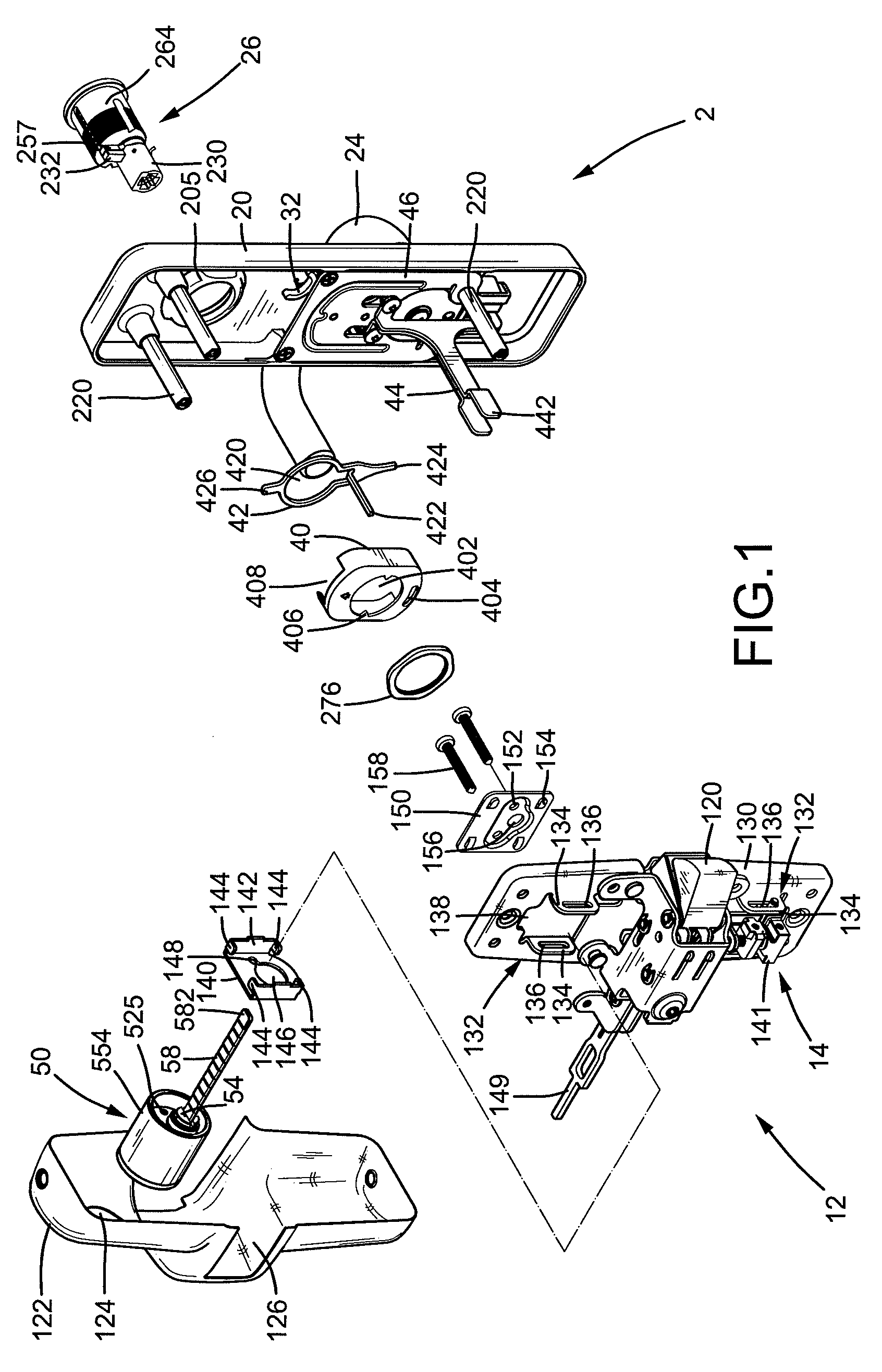
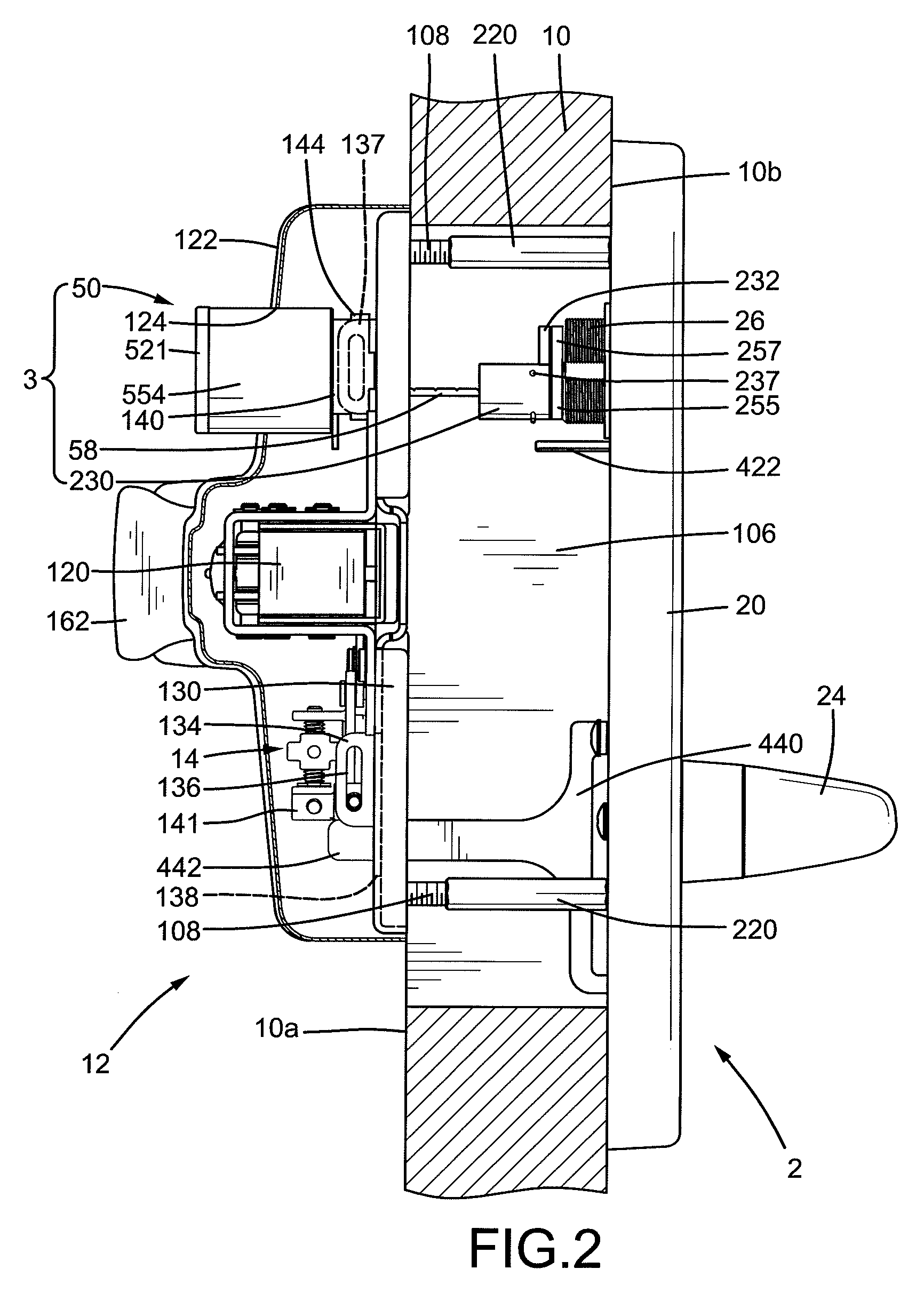
[0027]A panic exit door lock according to the preferred teachings of the present invention is shown in the drawings and adapted to be mounted to a door 10 in the preferred form shown as a panic exit door. According to the preferred form shown, the lock includes a latch device 12 mounted to an inner side 10a of door 10, an outer operational device 2 mounted to an outer side 10b of door 10, and a locking mechanism 3 mounted between latch device 12 and outer operational device 2. Door 10 includes a mounting hole 106 for receiving components of latch device 12, locking mechanism 3, and outer operational device 12. Latch device 12 allows a user to open door 10 from inner side 10a, outer operational device 2 allows the user to open door 10 from outer side 10b, and locking mechanism 3 allows the user to set the lock in a locked state or unlock from inner side 10a or outer side 10b. When the lock is in the locked state, door 10 can not be opened through operation of outer operational device...


PUM


Abstract

A panic exit door lock includes a cover (20) mounted to an outer side (10b) of a door (10). A sliding member (34) is slideably received in the cover (20) and operably connected to a latch (12). A handle (24) is pivotably mounted to the cover (20) and operably connected to the sliding member (34) such that rotation of the handle (24) causes sliding of the sliding member (34) to move the latch between an extended position and a retracted position. A limiting member (32) is pivotably received in the cover (20) between a blocking position not allowing movement of the sliding member (34) and a release position allowing movement of the sliding member (34). An inner lock core (54) and an outer lock core (270) are respectively mounted to an inner side (10a) and the outer side (10b) of the door (10). Either of the inner and outer lock cores (54, 270) can be rotated by a key to move the limiting member (32) between the blocking position and the release position.

Description

BACKGROUND OF THE INVENTION[0001]The present invention relates to a panic exit door lock and, more particularly, to a panic exit door lock that allows locking on both inner and outer sides of a panic exit door for deadlocking purposes.[0002]Panic exit door locks generally include an outer operational device that provides a deadlocking effect through a setting operation from an outer side of a panic exit door. An example of the lockable panic exit door locks is disclosed in U.S. patent application Ser. No. 12 / 264,310 filed Nov. 14, 2008. However, the deadlocking function of the conventional locks can not be set or removed from an inner side of the panic exit door.[0003]Thus, a need exists for a panic exit door lock that allows locking on both inner and outer sides of a panic exit door for deadlocking purposes.BRIEF SUMMARY OF THE INVENTION[0004]The present invention solves this need and other problems in the field of deadlocking function setting of panic exit door locks by providing,...

Claims


Application Information

Patent Timeline
IPC IPC(8): E05B65/10
CPCE05B3/065E05B13/004E05B65/10E05B17/04E05B15/02Y10S70/60Y10T70/5159Y10T70/5226Y10T70/5243Y10T70/5394Y10T70/5473Y10T70/577Y10T70/7706Y10T70/7712Y10T70/8946Y10T292/0822Y10T292/0908Y10T292/57
Inventor TIEN, HUNG-JEN
Owner I TEK METAL MFG
Why Eureka
Try Eureka