Dropper bottle and accessories therefor

a technology of dropper bottle and dropper head, which is applied in the field of dropper bottles, can solve the problems of difficult to obtain accurate control and dose placement, difficult to repeatedly control the volume of dropper bottle, etc., and achieve the effect of improving the administration of eye drops, repeatable and reliable manner, and protecting the eye of users from potential damag

Inactive Publication Date: 2009-12-22
COHEN BEN Z
View PDF9 Cites 24 Cited by
  • Summary
  • Abstract
  • Description
  • Claims
  • Application Information

AI Technical Summary

Benefits of technology

[0004]To overcome shortcomings of the prior art, the subject invention is provided which includes various dropper bottle designs and dropper bottle assemblies including accessories for dropper bottles. With certain aspects of the subject invention, improvements in the administration of eye drops is provided by adding accessories or modifications to conventional dropper bottles, so that doses and / or single drops may be administered in a repeatable and reliable manner. More specifically, certain embodiments restrict the amount the dropper bottle is deformed in administering a dose; other embodiments rely on mechanical reduction of interior volume (without deformation of the dropper bottle) to administer a dose, such as with a displaceable piston; and, yet, a further embodiment provides a valving arrangement to limit a dose. Further features are included which aid in the alignment of the dropper bottle's nozzle to the eye, and also protect the user's eye from potential damage which can occur if a pointed nozzle is brought into contact with the eye during alignment. As will be appreciated by those skilled in the art, the various aspects and embodiments disclosed herein may be used singularly or in various combinations.

Problems solved by technology

Although the conventional design is widely used, it suffers from several drawbacks.
Primarily, dose volume is difficult to repeatedly control, in part, because a proper amount of squeeze force is difficult to repeatedly apply to the dropper bottle.
Also, accurate control over and targeting of dose placement are difficult to obtain.

Method used


Image

  • Dropper bottle and accessories therefor
  • Dropper bottle and accessories therefor
  • Dropper bottle and accessories therefor

Examples


Embodiment Construction

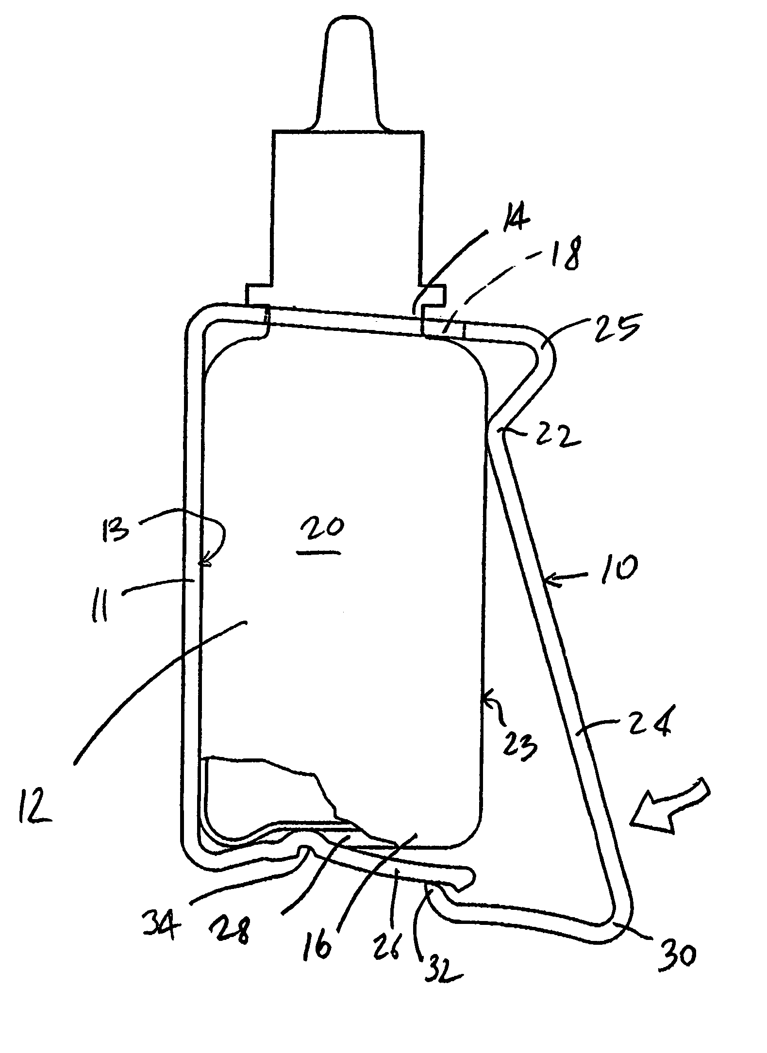
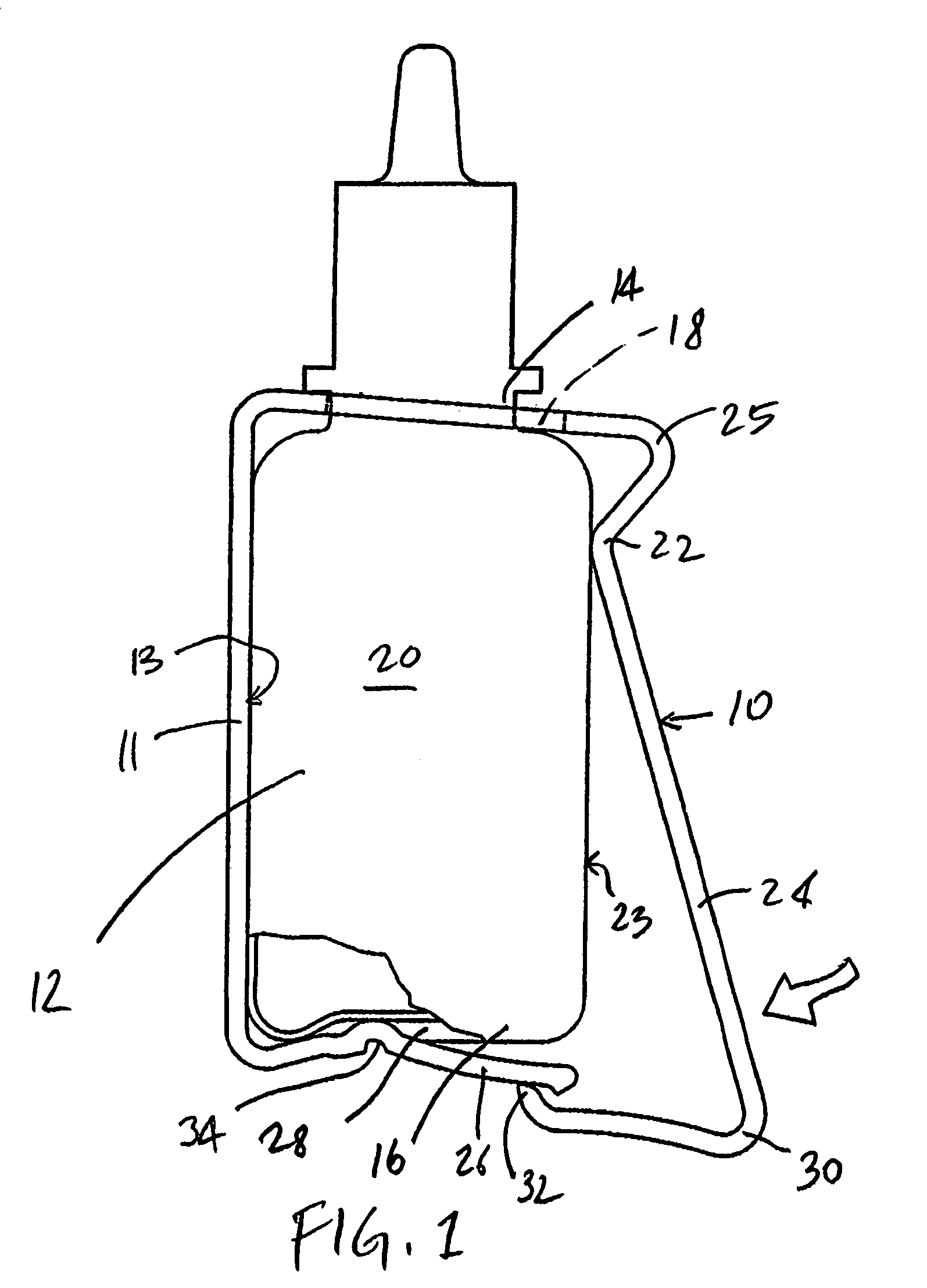
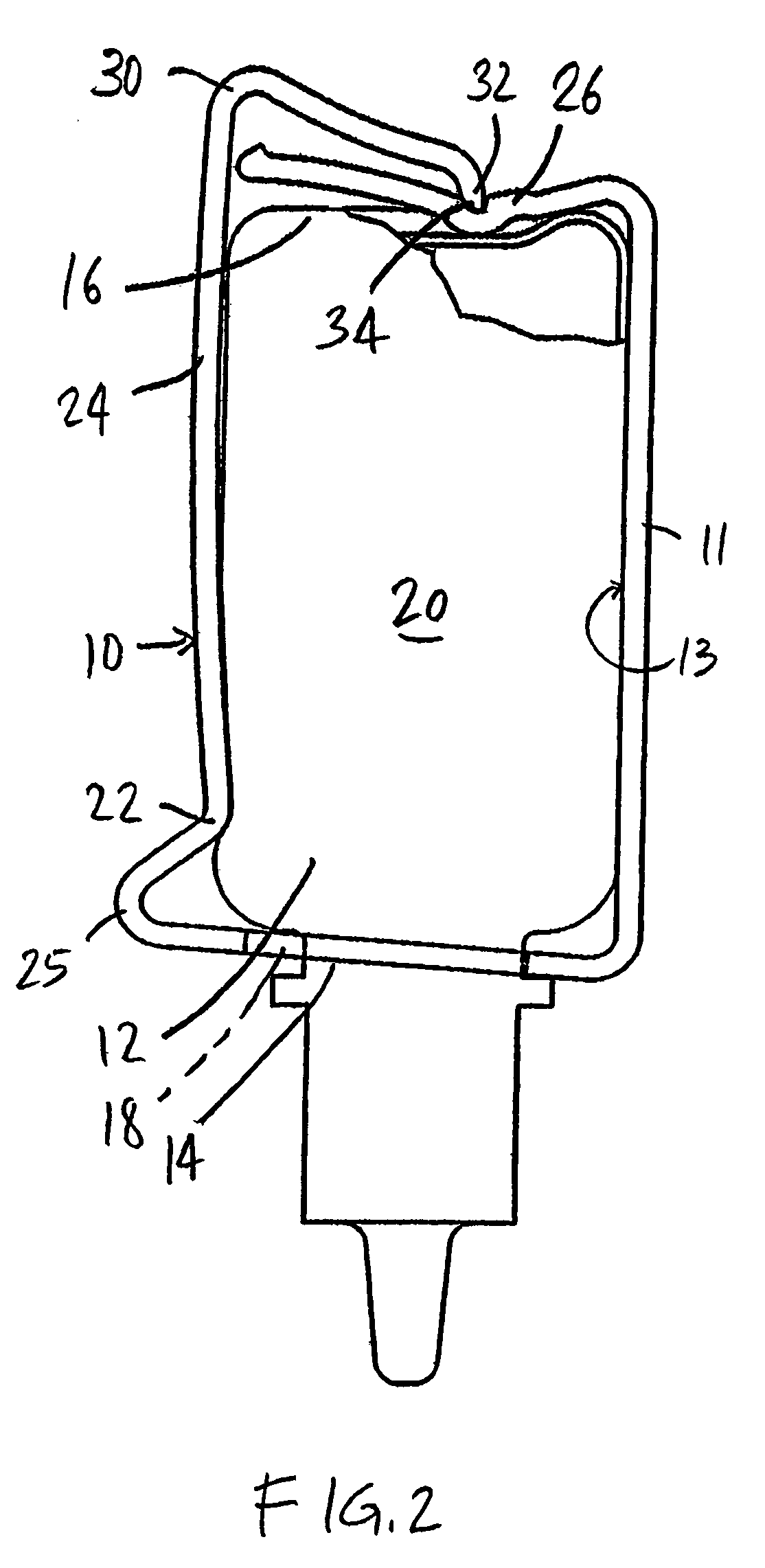
[0013]Several embodiments of the subject invention are directed to the problem that most current dropper bottles require the bottle to be deformed, e.g. squeezed, in order to generate pressure inside the bottle and, thereby, expel a dose or drop. This practice is problematic because the user is often unable to determine how hard to press the bottle, and for how long a period of time, so that a single drop is expelled. Usually, more than one drop is expelled, which may be wasteful and messy.

[0014]With reference to FIGS. 1-3, and in a first aspect of the subject invention, a cradle 10 is depicted which is formed to mount onto a dropper bottle 12 preferably by resiliently snapping onto the bottle 12 at the neck 14 and base 16. Preferably, the cradle 10 is formed of a resilient material, more preferably, a resilient thermoplastic. Mounting of the cradle 10 onto the neck 14 is facilitated by the provision of a hole 18 formed large enough to allow the bottle 12 to partially pass therethro...


PUM


Abstract

To overcome shortcomings of the prior art, the subject invention is provided which includes various dropper bottle designs and dropper bottle assemblies including accessories for dropper bottles. With certain aspects of the subject invention, improvements in the administration of eye drops is provided by adding accessories or modifications to conventional dropper bottles, so that doses and / or single drops may be administered in a repeatable and reliable manner. More specifically, certain embodiments use devices (10, 300) to restrict the amount the dropper bottle (12) is deformed in administering a dose; other embodiments rely on mechanical reduction of interior volume (without deformation of the dropper bottle (12)) to administer a dose, such as with a displaceable piston (500, 602); and, yet, a further embodiment provides a valving arrangement (402, 404) to limit a dose. Features (200) are also included which aid in the alignment of the dropper bottle's nozzle to the eye, and a feature (102) is provided for protecting the user's eye from potential damage which can occur if a pointed nozzle (104) is brought into contact with the eye during alignment. As will be appreciated by those skilled in the art, the various aspects and embodiments disclosed herein may be used singularly or in various combinations.

Description

[0001]This application claims priority to U.S. Provisional Patent Application No. 60 / 401,397, filed Aug. 6, 2002.[0002]Conventional dropper bottles for administering ophthalmic fluid are well known in the prior art. The basic commercial design of such dropper bottles has remained fairly unchanged over the last several decades: a squeezable container is provided with a tapered dispenser that terminates in a discharge aperture. To administer ophthalmic fluid, the discharge aperture is aligned above a target eye and the bottle is squeezed to urge out a drop or dose of the fluid.[0003]Although the conventional design is widely used, it suffers from several drawbacks. Primarily, dose volume is difficult to repeatedly control, in part, because a proper amount of squeeze force is difficult to repeatedly apply to the dropper bottle. Also, accurate control over and targeting of dose placement are difficult to obtain.SUMMARY OF THE INVENTION[0004]To overcome shortcomings of the prior art, the...

Claims


Application Information

Patent Timeline
Patent Type & Authority Patents(United States)
IPC IPC(8): B67D5/64B67D7/84A61F9/00B65D1/32B65D23/00B65D47/18
CPCA61F9/0008B65D1/32B65D47/18B65D23/001B65D23/00
Inventor COHENKELLY, NIGEL
Owner COHEN BEN Z
Why Eureka
Try Eureka