Digital camera

a digital camera and camera body technology, applied in the field of digital cameras, can solve the problem that the flicker of a desired light source may not be detected

Inactive Publication Date: 2009-12-22
MONUMENT PEAK VENTURES LLC
View PDF15 Cites 29 Cited by
  • Summary
  • Abstract
  • Description
  • Claims
  • Application Information

AI Technical Summary

Benefits of technology

[0007]The present invention aims to provide a digital camera capable of accurately detecting flicker even during a period when a video image is displayed on a display device.
[0009]According to the present invention, the cycle of the second vertical synchronization signal is determined in accordance with the cycle of fluctuation in luminance level of the light source assumed as the light source of the object, and based on the second vertical synchronization signal the flicker detection circuit detects flicker of the light source illuminating the object. As a result, flicker of the light source can accurately be detected even while a video image is displayed on the display device.
[0011]According to the present invention, the video signal is output from the second group of pixel circuits while the cycle of the second vertical synchronization signal is successively switched in accordance with the determined cycle, and based on the video signal output in the different cycle the flicker detection circuit successively detects flicker of the light source. Consequently, even when a plurality of light sources having different cycles of fluctuation in luminance level are present in the light source assumed as the light source of the object, flicker of the light source can accurately be detected.
[0013]According to the present invention, for each second vertical synchronization signal having a different cycle, the pixel circuits individually output the video signal in a successive manner, and the flicker detection circuit detects flicker of the light source based on such a video signal. As a result, even when a plurality of light sources having different cycles of fluctuation in luminance level are present in the light source assumed as the light source of the object, flicker of the light source can be accurately detected.
[0015]According to the present invention, the flicker detection exposure period is determined in accordance with the cycle of fluctuation in luminance level of the light source assumed as the light source of the object independently from the display exposure period for the display video signal. Consequently, the flicker detection circuit can accurately detect flicker of the light source based on the flicker detection video signal without depending on the display exposure period for the display video signal.
[0017]According to the present invention, the flicker detection gain can be set at an appropriate value without depending on the display gain for the display video signal even when the flicker detection exposure period is set shorter for flicker detection than the display exposure period.

Problems solved by technology

Consequently, when flicker is detected by the flicker detection means disclosed in Patent Document 2 based on the divided image data items used for displaying an image on a viewfinder, flicker of a desired light source may not be detected.

Method used


Image

  • Digital camera
  • Digital camera
  • Digital camera

Examples


Embodiment Construction

[0034]Preferred embodiments of the present invention (hereinafter referred to as “embodiments”) will be described with reference to the accompanying drawings.

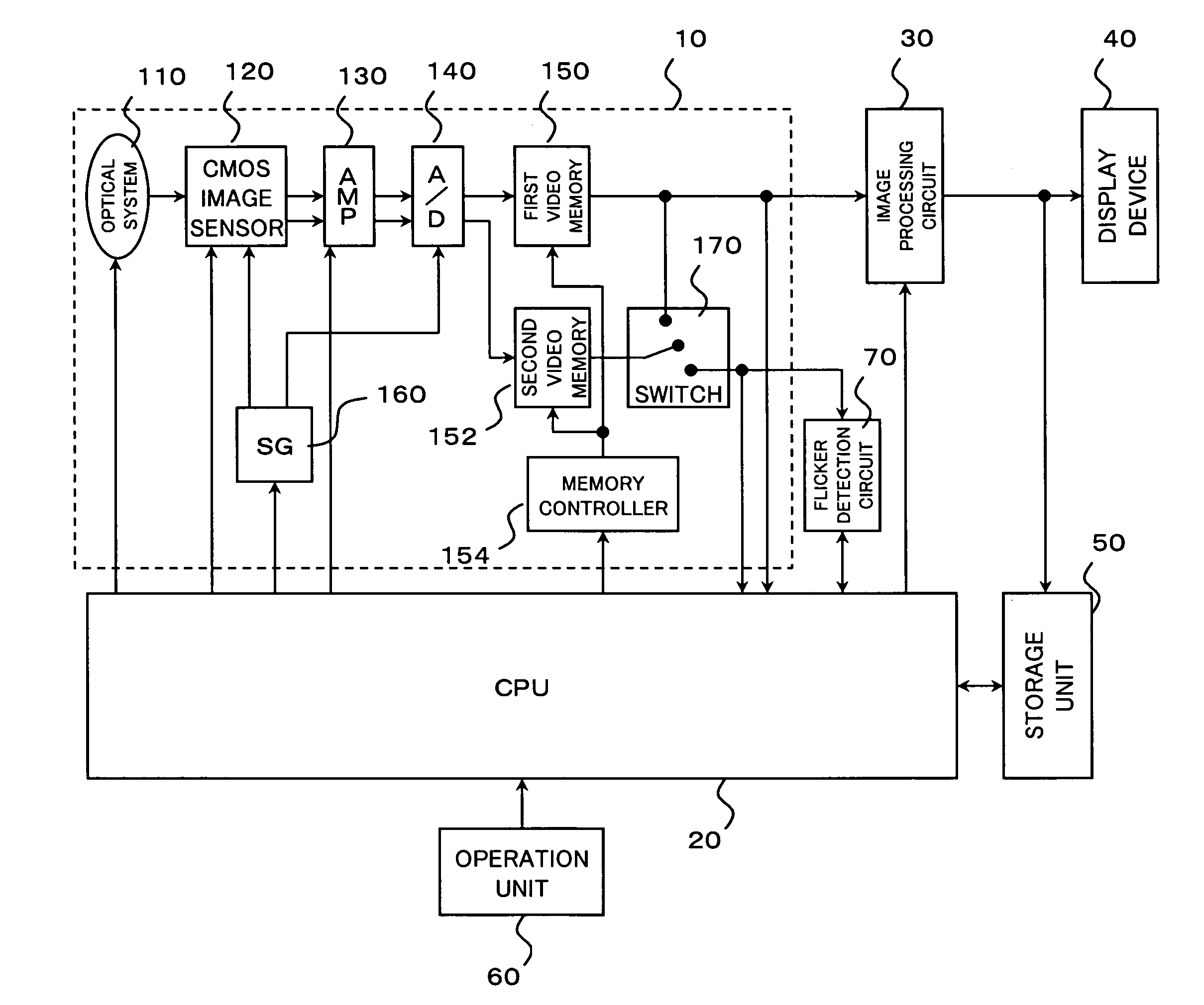
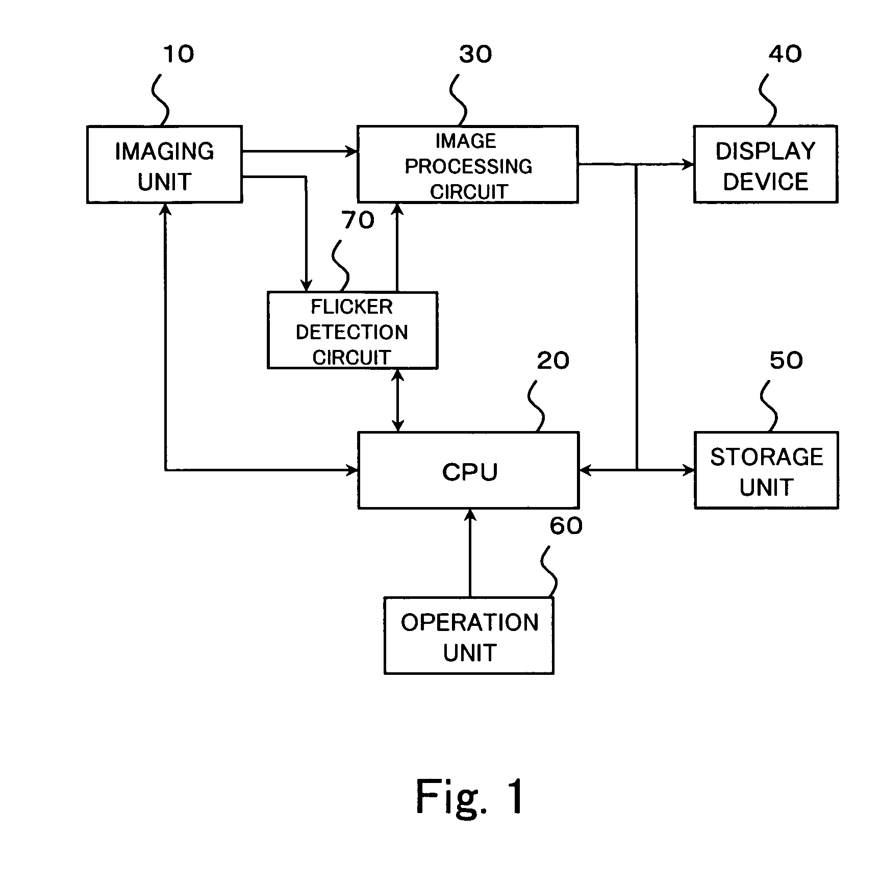
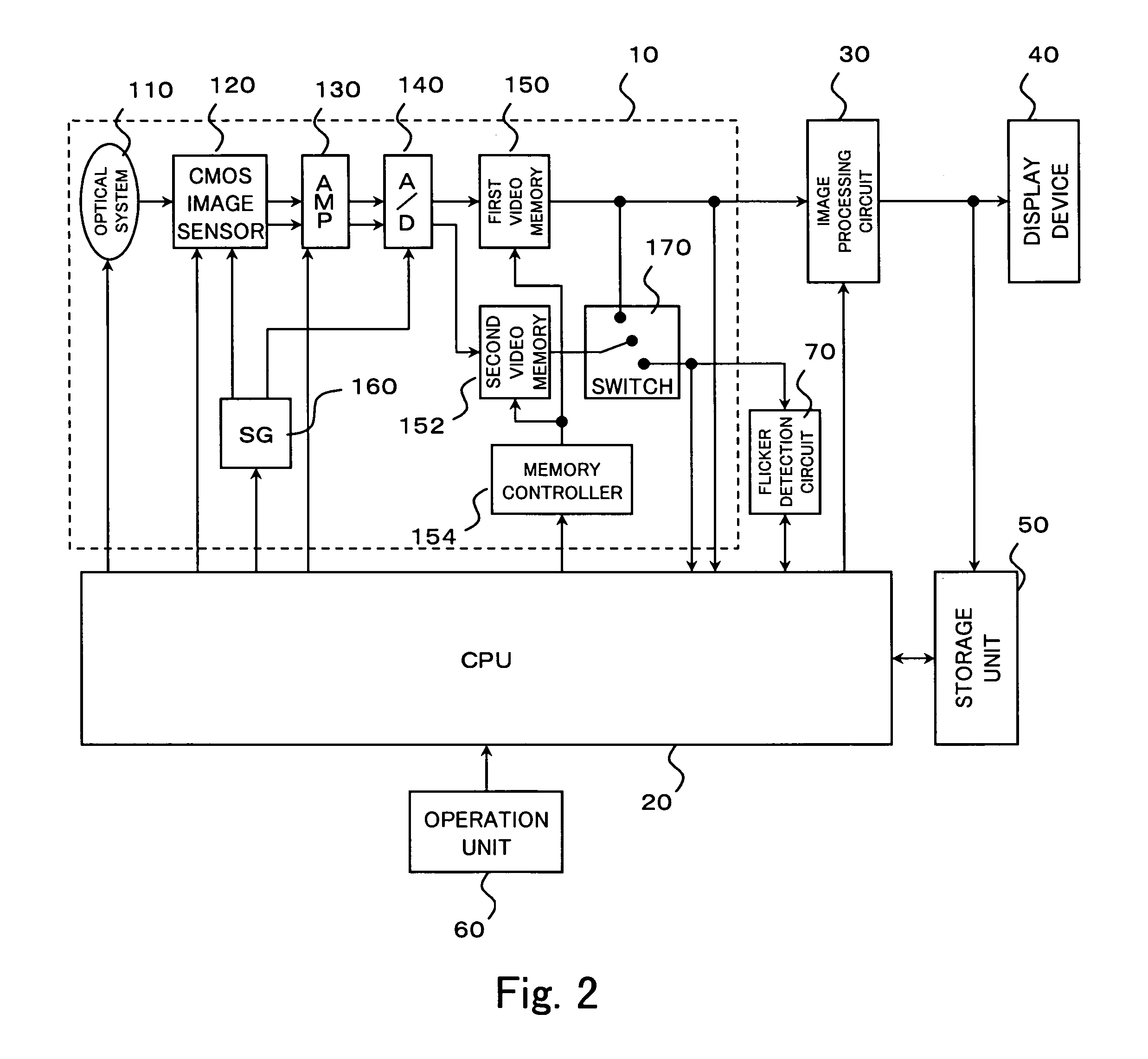
[0035]FIG. 1 is a functional block diagram of a digital camera according to the present embodiment. An imaging unit 10 receives light from an object under the control of a CPU 20, and supplies a video signal in accordance with the received light. The CPU 20 is a central processing unit controlling the entire digital camera for performing arithmetic operations for each circuit, controlling these circuits, and the like. An image processing circuit 30 performs predetermined image processing, such as white balance adjustment, on a video signal, and provides the resulting image data. A display device 40 sequentially displays a video image based on the image data to function as a viewfinder for photographing. A storage unit 50 records image data. An operation unit 60 is a user interface for a user to operate the digital camera when h...


PUM


Abstract

A digital camera capable of accurately detecting flicker even while a video image is displayed on a display device is provided. In a digital camera, a video image is displayed on a display device 40 serving as a viewfinder for photographing based on a display video signal supplied from a CMOS image sensor 120 while image data based on a recording video signal supplied from the CMOS image sensor 120 is recorded in a recording unit 50. The digital camera detects flicker based on a video signal supplied from a group of pixel circuits which do not supply the display video signal among the group of pixel circuits forming the CMOS image sensor 120.

Description

FIELD OF THE INVENTION[0001]The present invention relates to digital cameras, such as an electronic still camera and a video camera.BACKGROUND OF THE INVENTION[0002]Common fluorescent lights flashing with a commercial AC power source repeatedly blink at a cycle of 1 / 100th of a second and 1 / 120th of a second when the frequency of the power source is 50 Hz and 60 Hz, respectively. When such incident light is converted into an electrical signal and read by an image pickup device, an exposure initiation time is varied with the position of the readout pixel when an image pickup tube or a MOS type solid-state image sensing device is used, as a result of which the total sum of the amount of light entering within the exposure time of each pixel is varied even in the same frame. As a result, a single frame has a bright portion and a dark portion at the cycle of 1 / 100th of a second or 1 / 120th of a second, and such a phenomenon is called flicker.[0003]Japanese Patent Laid-Open Publication No. ...

Claims


Application Information

Patent Timeline
Patent Type & Authority Patents(United States)
IPC IPC(8): H04N9/73H04N5/335H04N5/232H04N5/235H04N5/341H04N5/351H04N5/357H04N5/369H04N5/374H04N5/376H04N101/00
CPCH04N5/2351H04N9/735H04N5/2357H04N23/745H04N23/71H04N23/88
Inventor NAKAJIMA, KENICHISAKURAI, JUNZOU
Owner MONUMENT PEAK VENTURES LLC
Why Eureka
Try Eureka