
Container holding device

a technology of holding device and container, which is applied in the field of container holding device, can solve the problems of impracticality of packing a cooler or ice chest which is large enough to carry a sufficient number of beverages, and achieve the effects of convenient, quick and inexpensive way to cool beverages, convenient use, and convenient storag

Inactive Publication Date: 2009-12-29
DOSS BRIAN EDWARD
View PDF8 Cites 11 Cited by
  • Summary
  • Abstract
  • Description
  • Claims
  • Application Information

AI Technical Summary

Benefits of technology

[0003]The container holding device is designed to be a quick, easy and inexpensive way to cool beverages. In many situations, packing a cooler or chest of ice which is large enough to carry a sufficient number of beverages is impractical, such as on a golf trip, while camping or on a boat, to name a few. By using the container holding device, a small cooler can be sufficient to cool many beverages.
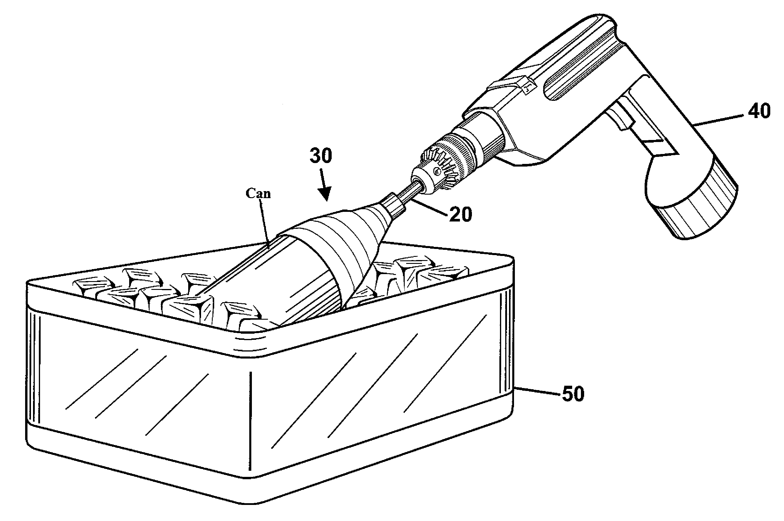
[0004]The present invention is comprised of two simple elements: a gripping device and a drive shaft. The gripping device is adapted to frictionally grip a beverage container, whether it be a can or a bottle. Extending from the gripping device is a drive shaft which is designed to fit into the chuck of a hand held motorized rotary device, such as a cordless drill. Use of the present invention is achieved by inserting and securing the drive shaft into the chuck of the hand held motorized rotary device and inserting the beverage to be cooled into the gripping device. The beverage is then inserted into an ice chest or icy solution. By activating the motorized rotary device, the drive shaft of the present invention is rotated, which in turn rotates the gripping device holding the container of liquid. This rotation of the container of liquid in the ice chest effectively transfers the heat from the liquid into the icy solution and quickly cools the beverage for more palatable consumption.

Problems solved by technology

In many situations, packing a cooler or chest of ice which is large enough to carry a sufficient number of beverages is impractical, such as on a golf trip, while camping or on a boat, to name a few.

Method used


Image

  • Container holding device
  • Container holding device
  • Container holding device

Examples


Embodiment Construction

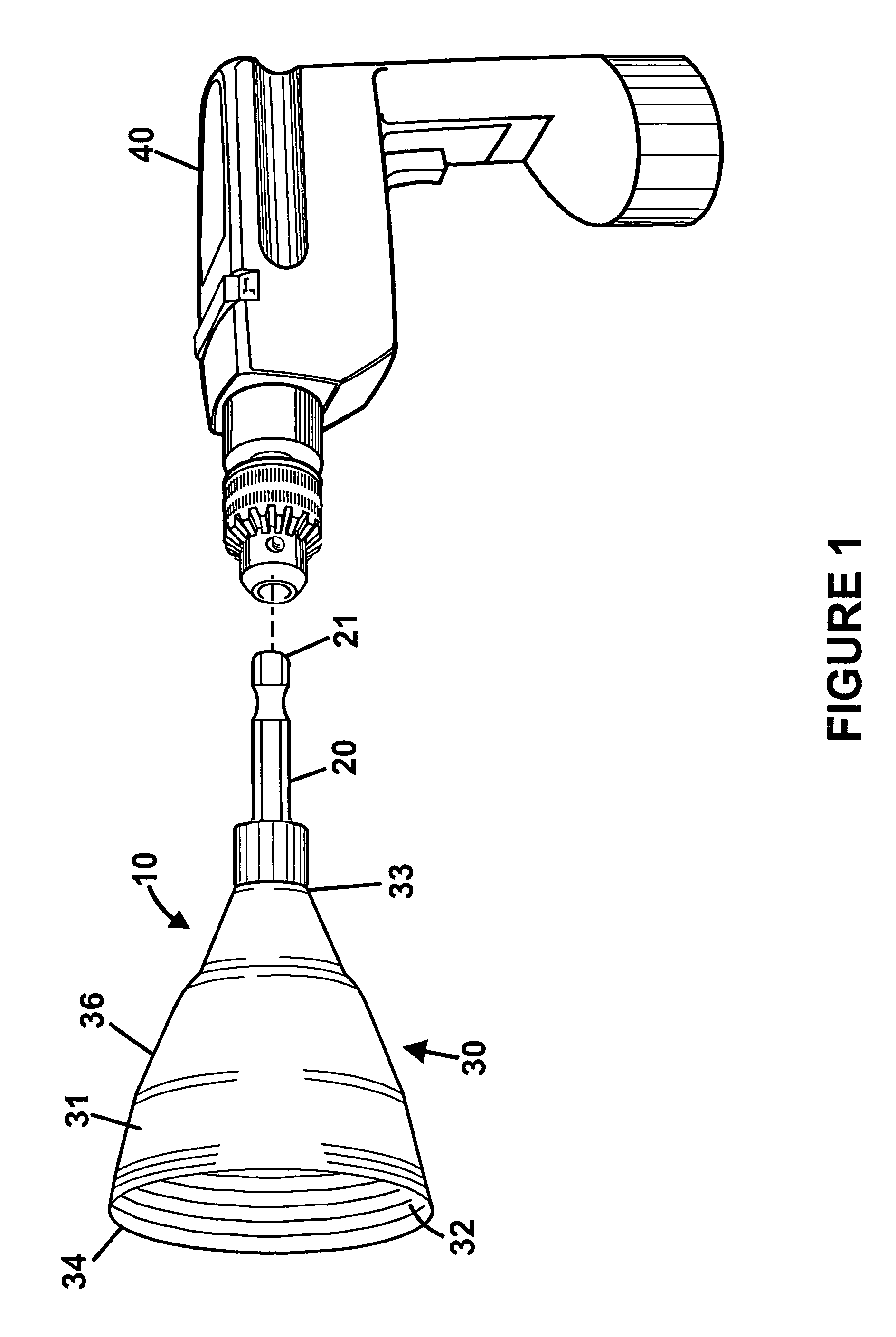
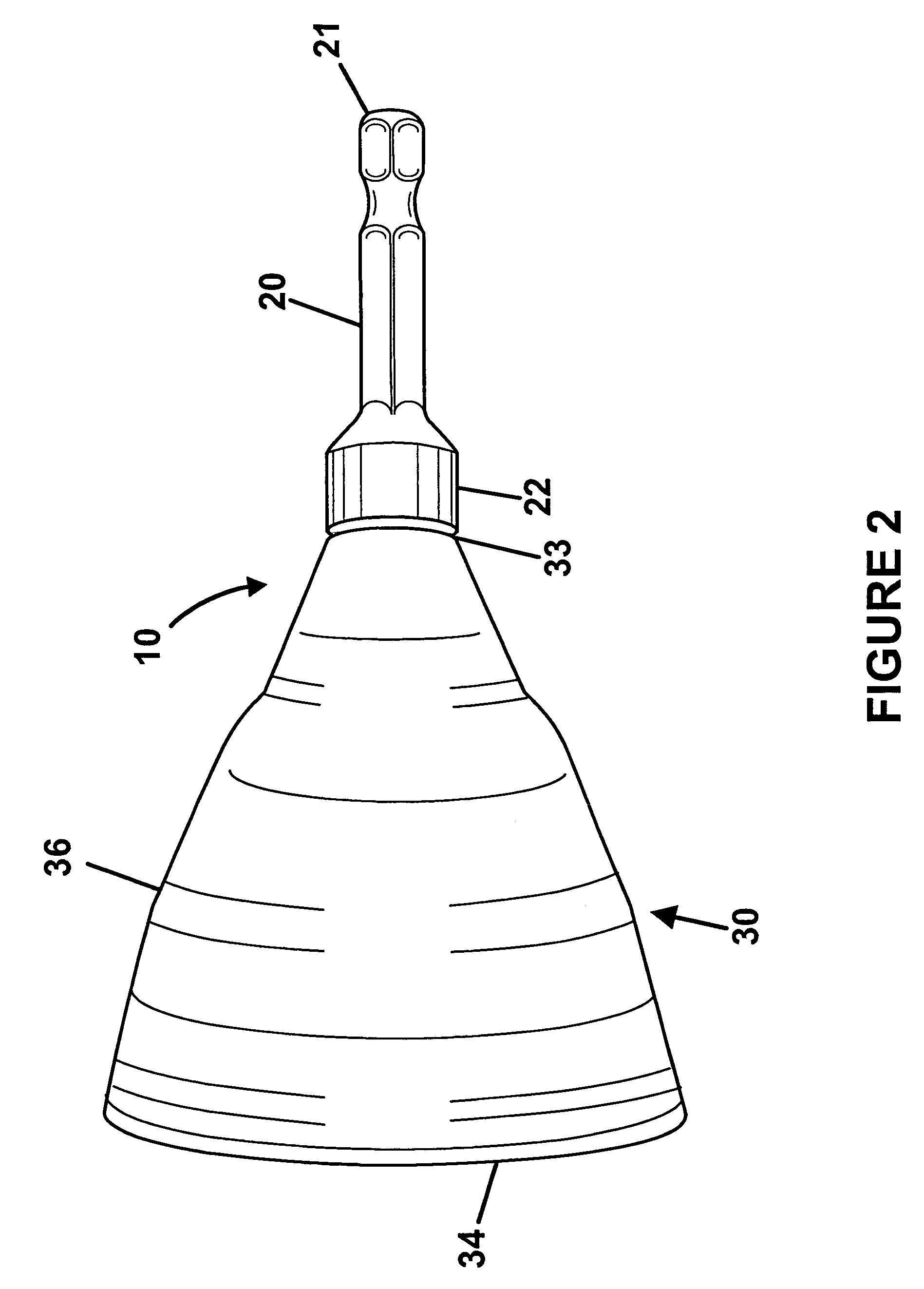
[0014]As is shown in FIG. 1 and FIG. 2, the present invention is comprised of a gripping device 30 attached to a drive shaft 20, which can be inserted into the chuck of a hand held motorized rotary device 40. The portion of the present invention which holds the container is the gripping device 30 and is typically made of a plastic, elastomer material, polymer, copolymer, rubber, aluminum and / or aluminum alloys or any material with sufficient strength and similar properties. FIG. 3 and FIG. 5 show an embodiment of the gripping device 30, which is essentially an open cavity which extends from a wide second end 34 to a narrow first end 33. The second end 34 has a larger diameter than the first end 33. The gripping device 30 can be shaped in a variety of structures which would frictionally hold a container. FIG. 2 and FIG. 5 show the gripping device 30 in the shape of a cone 36. FIG. 7 shows the gripping device 30 in the shape of a tapered cylinder 37, and FIG. 8 shows a gripping device...


PUM


Abstract

The container holding device is designed to improve the process of cooling liquids within containers. The present invention comprises a gripping device, which holds a container of fluid, and a drive shaft which is designed so that it can be securely inserted into the chuck of a hand held motorized rotary device. The inner surface of the gripping device frictionally retains a container securely, while the container is submerged into a chest filled with ice or an icy water solution and the hand held motorized rotary device actuated. The rotation accelerates the transference of the heat from the container into the colder ice or icy solution. A detachable handle, capable of connecting to the drive shaft, may also be used to allow the user to manually spin the container of fluid if a hand held motorized rotary device is not available.

Description

BACKGROUND OF THE INVENTION[0001]The present invention relates primarily to a container holding device which can be attached to any standard hand held motorized rotary device and used to quickly cool the liquid in the container. The present invention uses a common household tool which can be easily transported to a remote location, such as camping, on a golf course or on a boat.[0002]All of the devices in the prior art require use of a permanently attached rotary device to rotate a can for cooling within an ice chest. The present invention is simple in design and uses a hand held motorized rotary device which is already present in nearly every household. This feature makes the present invention much more economical to manufacture and easier to transport.SUMMARY OF THE INVENTION[0003]The container holding device is designed to be a quick, easy and inexpensive way to cool beverages. In many situations, packing a cooler or chest of ice which is large enough to carry a sufficient number...

Claims


Application Information

Patent Timeline
Patent Type & Authority Patents(United States)
IPC IPC(8): F25D25/00
CPCF25D3/02F25D31/007F25D2400/28F25D2331/805F25D2303/081
Inventor DOSS, BRIAN EDWARD
Owner DOSS BRIAN EDWARD
Learn More