Image processor, method for informing status change of image processor and computer program product

a technology of image processor and status change, applied in the field of image processor, can solve the problems of error message sent to the device, difficult to introduce efficiently a newly added function of image processor to users who use the image processor, and difficult to decide which user should be informed of a newly added function

Active Publication Date: 2009-12-29
KONICA MINOLTA BUSINESS TECH INC
View PDF39 Cites 7 Cited by
  • Summary
  • Abstract
  • Description
  • Claims
  • Application Information

AI Technical Summary

Benefits of technology

[0016]An object of the present invention is to inform a user efficiently of a change such as an addition of a new function to an image processor.
[0019]According to the present invention, when a change such as addition of a new function is generated in an image processor, a notice of the change can be sent to a user efficiently.

Problems solved by technology

Then, an error message is sent to the devices.
Then, if the abnormal operation has not resolved yet, error information is sent to a host computer that sent the print data that was being processed at the time when the abnormal operation was detected or a host computer that sent print data before or after the time.
However, according to the conventional method as described in each of the above-mentioned patent publication, it is difficult to introduce efficiently a newly added function of the image processor to users who use the image processor.
However it is difficult to decide which user should be informed of a newly added function by these methods.
However, it is also difficult to decide which user should be informed of a newly added function by these methods.
In addition, some users may feel it burdensome to receive all notices because they are not always important to each of the users.

Method used


Image

  • Image processor, method for informing status change of image processor and computer program product
  • Image processor, method for informing status change of image processor and computer program product
  • Image processor, method for informing status change of image processor and computer program product

Examples


Embodiment Construction

[0034]Hereinafter, the present invention will be explained more in detail with reference to embodiments and drawings.

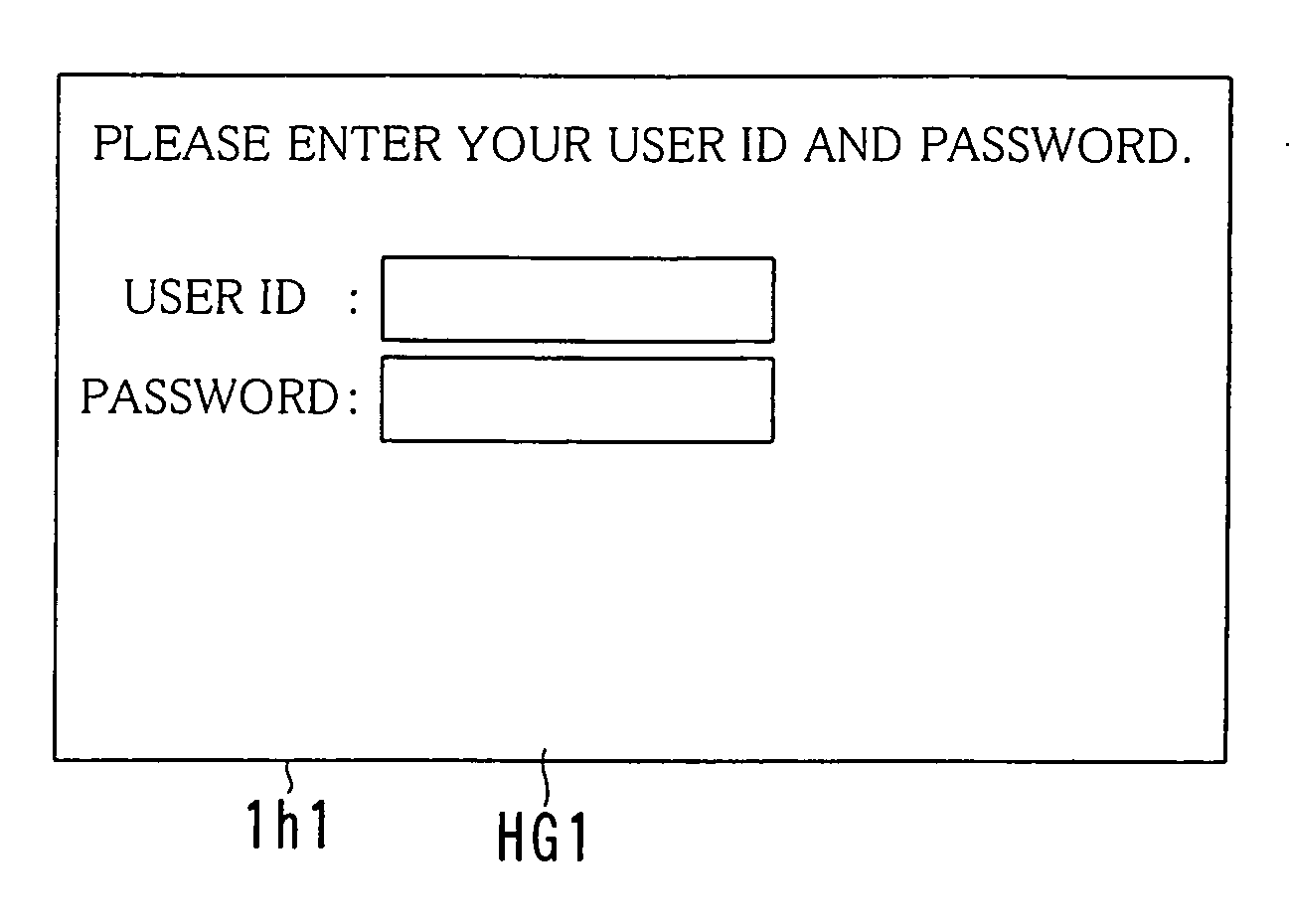
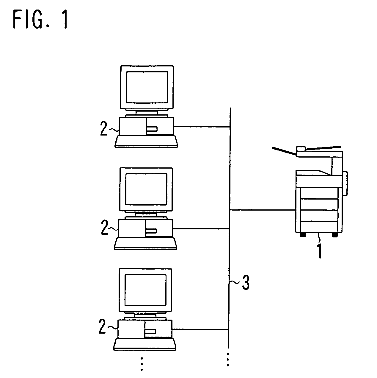
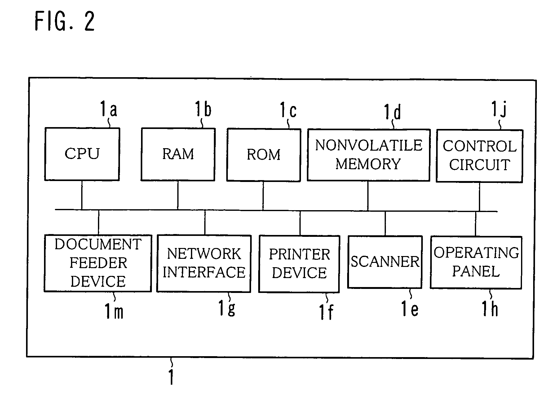
[0035]FIG. 1 shows an example of an overall structure of a network system equipped with an image forming device 1 according to the present invention, FIG. 2 shows an example of a hardware structure of the image forming device 1, FIG. 3 shows an example of a structure of an operating panel 1h, FIG. 4 shows an example of a functional structure of the image forming device 1.

[0036]The image forming device 1 according to the present invention is connected to a terminal device 2 via a communication line 3 as shown in FIG. 1. As the communication line 3, a LAN, the Internet, a public telephone line or a private line can be used. As a protocol, FTP (File Transfer Protocol), POP (Post Office Protocol) or SMTP (Simple Mail Transfer Protocol) can be used.

[0037]The image forming device 1 is a device including integrated functions of a copy, network printing, a scanner or the like...


PUM


Abstract

An image forming device includes a user job history database for storing execution condition information that indicates an execution condition of the job in relationship with user identification information for distinguishing a user who made the instruction for each executed job, a device structure detection portion for detecting a change in a state of the image processor, a notification target determination portion for determining a notification target user who is a user to be notified of the change in accordance with the execution condition information and the user identification information stored in the user job history database, and a new function notification portion for notifying the change to the determined notification target user.

Description

[0001]This application is based on Japanese Patent Application No. 2004-295446 filed on Oct. 7, 2004, the contents of which are hereby incorporated by reference.BACKGROUND OF THE INVENTION[0002]1. Field of the Invention[0003]The present invention relates to an image processor such as multifunction peripherals that can send data to a terminal device of a user via a network and a method for controlling the image processor.[0004]2. Description of the Prior Art[0005]Recently, an image processor such as a printer or a copying machine is equipped with various functions. For example, an image processor is proposed that has a scanner function, a FAX function, or a document server (box) function adding to a conventional copy function and a network printing function. Such an image processor is called a multifunction device or multifunction peripherals (MFP).[0006]Some image processors have all the above-mentioned functions as standard functions, while other image processors support a part of ...

Claims


Application Information

Patent Timeline
Patent Type & Authority Patents(United States)
IPC IPC(8): G06F3/12G06F3/00H04N1/00
CPCH04N1/00007H04N1/00037H04N1/00204H04N1/00079H04N2201/0094H04N2201/0039
Inventor NAKATA, HIRONOBUMURAKAMI, MASAKAZUSAWAYANAGI, KAZUMIKOBAYASHI, MINAKO
Owner KONICA MINOLTA BUSINESS TECH INC
Why Eureka
Try Eureka