Dispensing device for adhesive tape

a dispenser and tape technology, applied in the field of adhesive tape dispensers, can solve the problems of potential hazard to users, contamination of tape, etc., and achieve the effects of reducing the contact area with the tape, convenient unfolding, and safe and convenient carrying

Active Publication Date: 2010-01-05
CHANG CHI TSAI
View PDF15 Cites 17 Cited by
  • Summary
  • Abstract
  • Description
  • Claims
  • Application Information

AI Technical Summary

Benefits of technology

[0004]Accordingly, the present invention provides a dispensing device for safe and convenient carry. The dispensing device has a flat cylindrical base member with a coaxial axle element inside for the mounting of a roll of adhesive tape. Along the wall of the cylindrical base member, a slit in the axial direction is provided through which a segment of the tape is pulled out. On a section of the wall adjacent to the slit, a curved rectangular buckle matching the curvature of the wall is hinged to the wall, which can be flipped away from the slit to be held at an appropriate included angle with the wall. A cutting blade is provided along the outer edge of the buckle parallel to the slit for cutting the exposed segment of the tape while the end of the remaining exposed segment of the tape is automatically adhered to the edge of the buckle. When the buckle is closed to the wall, the remaining exposed segment of the tape is folded between the buckle and the section of wall. The interfacing surfaces of the buckle and the section of the wall are patterned to reduce the contact area with the tape and the folded segment of the tape can be easily unfolded when the buckle is flipped open again.

Problems solved by technology

This is especially troublesome if the tape is for medical purpose and contamination to the tape may be an issue.
In addition, as the cutting blade 33 is exposed openly, it presents a potential hazard to the user.

Method used


Image

  • Dispensing device for adhesive tape
  • Dispensing device for adhesive tape
  • Dispensing device for adhesive tape

Examples


Embodiment Construction

[0013]The following description are exemplary embodiments only, and are not intended to limit the scope, applicability or configuration of the invention in any way. Rather, the following description provides a convenient illustration for implementing exemplary embodiments of the invention. Various changes to the described embodiments may be made in the function and arrangement of the elements described without departing from the scope of the invention as set forth in the appended claims.

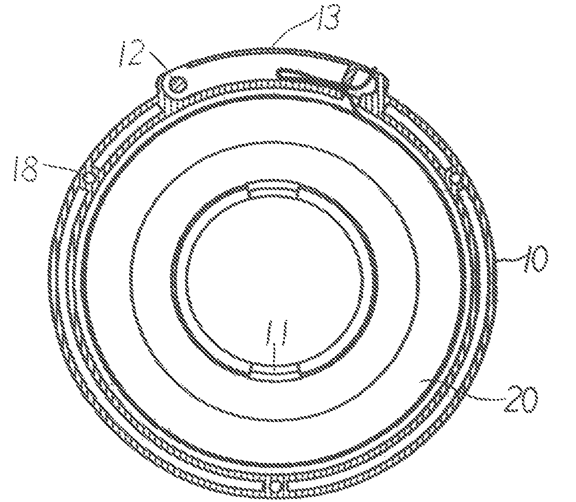
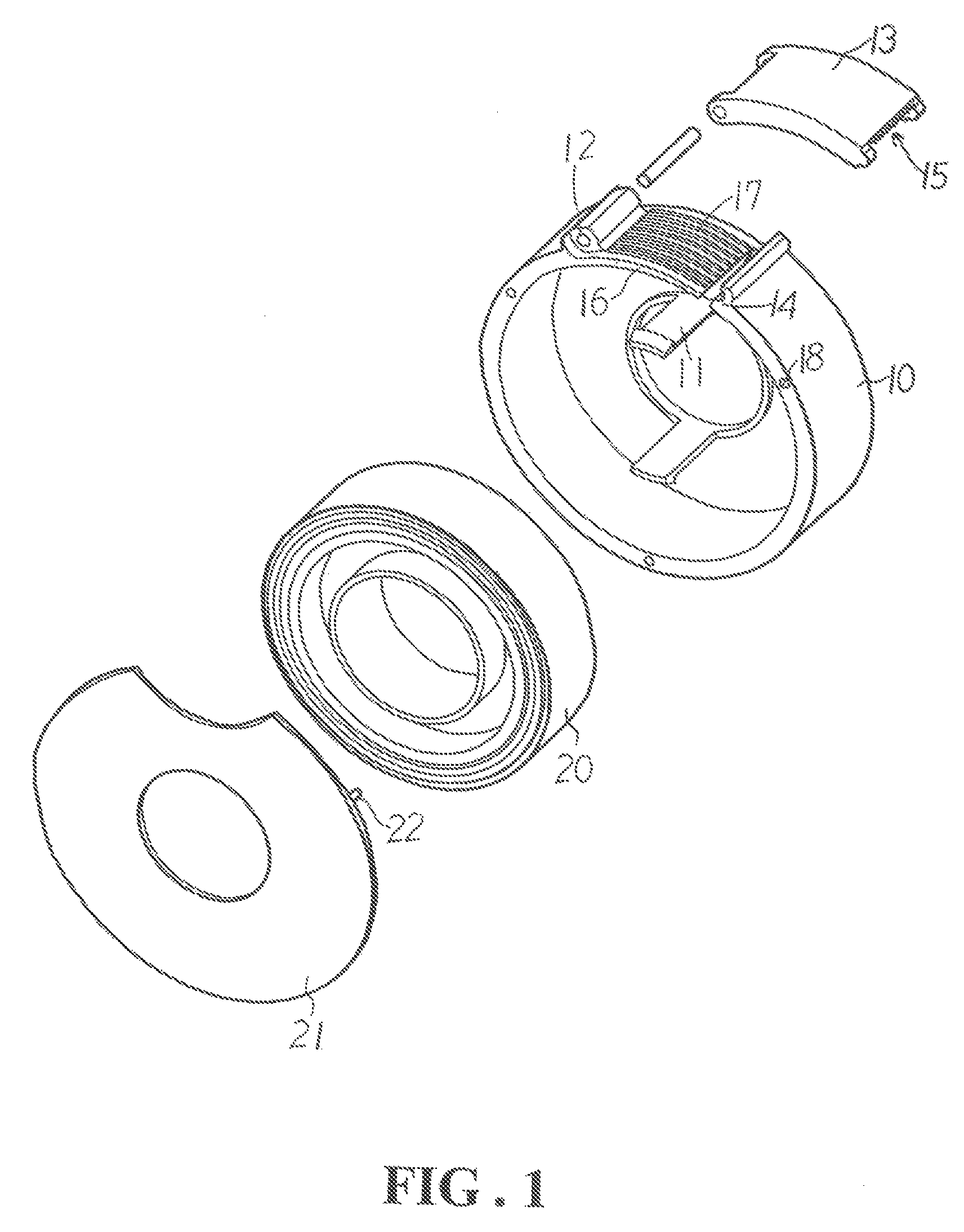
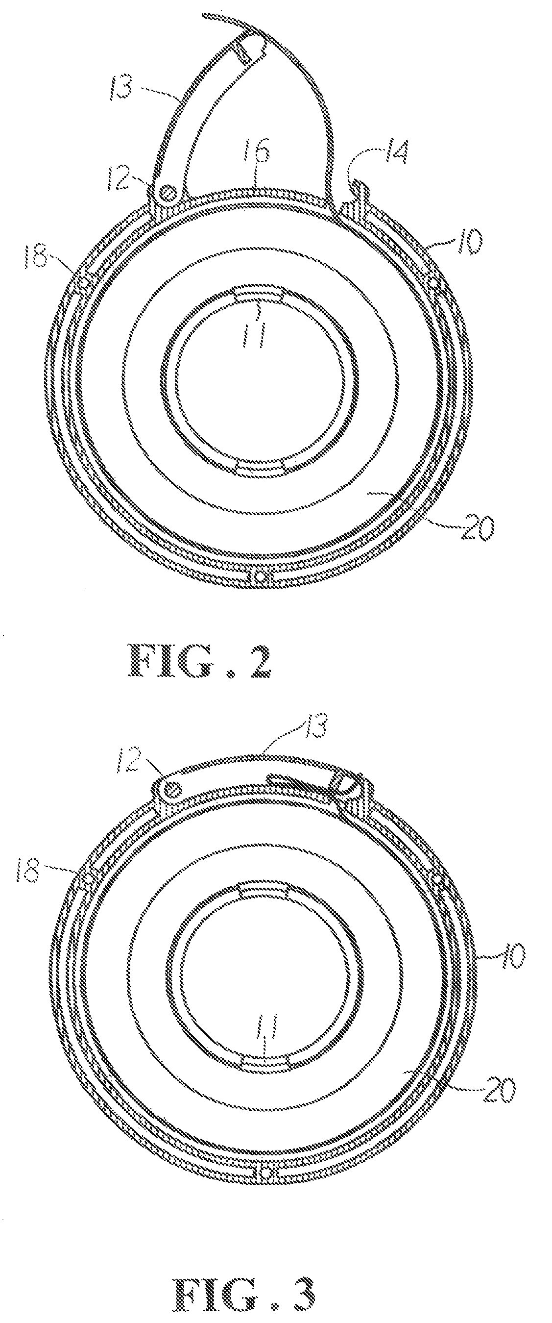
[0014]As illustrated in FIG. 1, a dispensing device according to an embodiment of the present invention for a roll of adhesive tape 20 has a base member 10, usually integrally formed by plastic molding. The base member 10 preferably has a shape compatible to that of the roll of adhesive tape 20. In the present embodiment, therefore, the base member 10 contains a disk having a center through hole and a circular wall perpendicularly extended from the rim of the disk. A number of elongated retaining sti...


PUM


Abstract

A dispensing device for adhesive tape has a flat cylindrical base member with a coaxial axle element inside for the mounting of a roll of adhesive tape. A slit is provided along the wall of the cylindrical base member through which the tape is pulled out. On a section of the wall adjacent to the slit, a curved rectangular buckle is hinged to the wall, which can be flipped away from the slit to be held at an appropriate included angle with the wall. A cutting blade is provided along the outer edge of the buckle for cutting the tape while the end of the remaining tape is automatically adhered to the edge of the buckle. When the buckle is closed to the wall, the exposed segment of the tape is folded between the buckle and the section of wall.

Description

TECHNICAL FIELD OF THE INVENTION[0001]The present invention generally relates to adhesive tape dispensers, and more particularly to a dispensing device where the adhesive tape and the cutting blade are concealed in a circular body member when not in use for safe and convenient carry.DESCRIPTION OF THE PRIOR ART[0002]As shown in FIG. 6, a conventional portable dispensing device for adhesive tape mainly contains a plastic body member 30 having a 9-like shape turned 90-degree clockwise. The body member 30 has two portions. In one portion, a tubular axle 31 is provided, on which a roll of adhesive tape 32 is mounted. A user can hold the portion in one hand and pulls out the tape by the other hand as the roll of adhesive 32 spins around the axle 31. On the other portion, a cutting blade 33 is provided having a sharp edge pointed upward. As such, the tape can be pulled to pass over and then cut by the blade 33. After cutting, the end of the remaining tape is automatically adhered to an in...

Claims


Application Information

Patent Timeline
Patent Type & Authority Patents(United States)
IPC IPC(8): B65H35/07
CPCB65H35/0026Y10T225/243Y10T225/254Y10T225/247
Inventor CHANG, CHI-TSAI
Owner CHANG CHI TSAI
Why Eureka
Try Eureka