Head rest device

a headrest and seat back technology, applied in the direction of pedestrian/occupant safety arrangements, vehicle components, vehicle arrangements, etc., can solve the problems of difficult to secure a space for placing the transmission means inside the seat back, difficult to raise the headrest with favorable responsiveness, etc., and achieve the effect of low rigidity

Inactive Publication Date: 2010-01-05
HONDA MOTOR CO LTD
View PDF21 Cites 19 Cited by
  • Summary
  • Abstract
  • Description
  • Claims
  • Application Information

AI Technical Summary

Benefits of technology

[0011]With the configuration according to the first feature, when the pressure receiving plate provided at the seat back is moved to a rear side of the vehicle body when the vehicle is collided from behind, the transmission means constructed by the long member transmits the movement of the pressure receiving plate to the headrest ascending mechanism as the tensile load. Therefore, the headrest is quickly raised to reliably hold the head of the occupant. Since the transmission means transmits only the tensile load, even if it is constructed by a long thin member with low rigidity, the transmission means is not buckled. Therefore, not only reduction in weight of the transmission means is possible, but also the degree of freedom of layout is increased. Since the transmission means is light in weight, it is not required to unreasonably dispose the pressure receiving plate at the position near the headrest ascending mechanism for reduction of weight, and the pressure receiving plate can be disposed at the optimal position where a sufficient drive force can be obtained upon a rear-end collision.
[0012]In further accordance with the present invention, the transmission means is constructed by the Bowden cable having flexibility, and therefore the transmission means can not only be made compact and light, but also the layout can be made easy so that the transmission means does not interfere with the other members in the seat back.

Problems solved by technology

Accordingly, unless a thick transmission means with high rigidity is used, there arises a possibility that the transmission means is bent and buckled when the headrest ascends, which not only makes it difficult to raise the headrest with favorable responsiveness but also makes it difficult to secure a space for placing the transmission means inside the seat back.

Method used


Image

  • Head rest device
  • Head rest device
  • Head rest device

Examples


Embodiment Construction

[0018]A mode of carrying out the present invention will be described based on an embodiment of the present invention shown in the attached drawings.

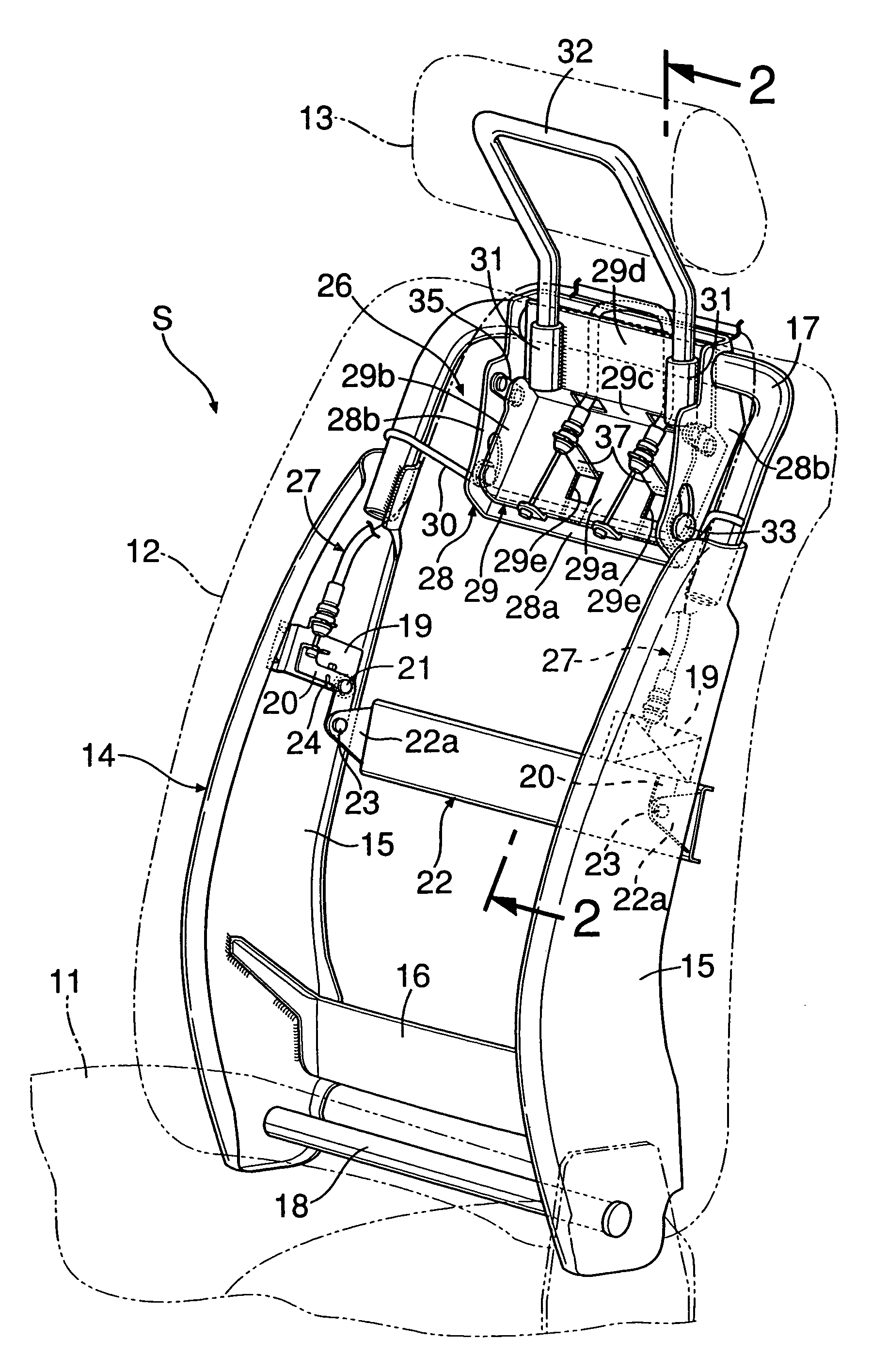
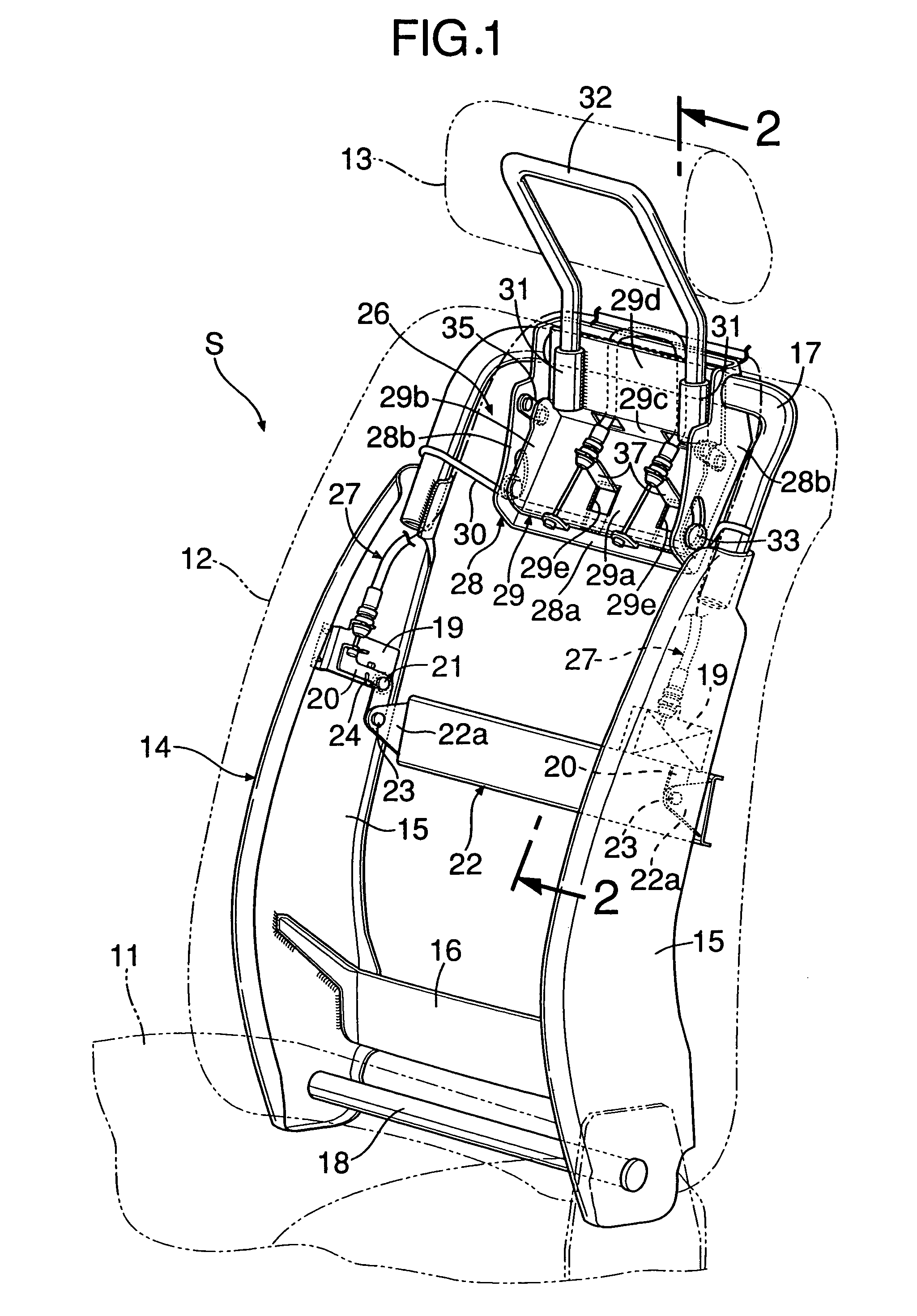
[0019]As shown in FIG. 1, a seat S for an automobile includes: a seat cushion 11 which supports buttocks of an occupant; a seat back 12 which is pivotally supported at a rear end of the seat cushion 11 to reclinably support a back of the occupant; and a headrest 13 which is provided at an upper end of the seat back 12 to ascendably support a head of the occupant.

[0020]A seat back frame 14 which constructs a framework of the seat back 12 includes: left and right side frames 15 and 15 made of a metal plate; a lower frame 16 made of a metal plate which connects lower ends of the left and right side frames 15 and 15; an upper frame 17 made of a metal pipe which connects upper ends of the left and right side frames 15 and 15; and a reclining shaft 18 for pivotally supporting the seat back 12 at the seat cushion 11.

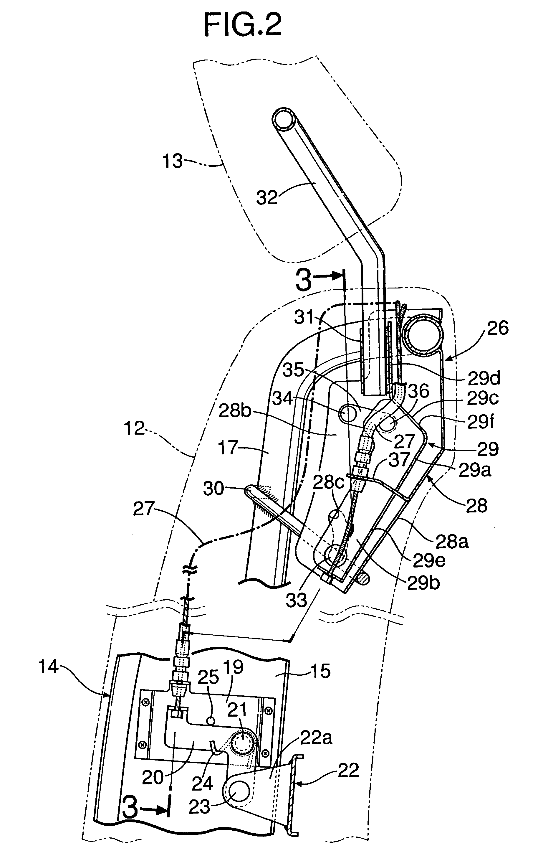
[0021]As is obvious from FIG...


PUM


Abstract

When a pressure receiving plate provided at a seat back moves to a rear side of a vehicle body when a vehicle is collided from behind, a Bowden cable transmits movement of the pressure receiving plate to a headrest ascending mechanism as a tensile load, thereby quickly ascending a headrest to reliably hold a head of an occupant. The Bowden cable transmits only the tensile load, and hence the Bowden cable is not buckled. Reduction in weight is made possible as compared with the case using a rod for transmitting a compression load. Since the Bowden cable is light, it is not required to unreasonably place the pressure receiving plate at a position near the headrest ascending mechanism for reduction in weight, and hence the pressure receiving plate can be placed at the optimal position where a sufficient driving force is obtained at the time of collision. Thus, a headrest is ascended with favorable responsiveness upon a rear-end collision of a vehicle while using a thin transmission member with low rigidity.

Description

RELATED APPLICATION DATA[0001]The Japanese priority application No. 2004-196234 upon which the present application is based is hereby incorporated in its entirety herein by reference.BACKGROUND OF THE INVENTION[0002]1. Field of the Invention[0003]The present invention relates to a headrest device comprising: a headrest ascending mechanism which ascendably supports a headrest at an upper end of a seat back; a pressure receiving plate which is provided at the seat back to face a back of an occupant and which moves to a rear side in a vehicle body by an inertia force upon a rear-end collision of a vehicle; and transmission means which connects the pressure receiving plate to the headrest ascending mechanism and which operates the headrest ascending mechanism to ascend the headrest when the pressure receiving plate moves to the rear side of the vehicle body.[0004]2. Description of the Related Art[0005]When a vehicle is struck from behind, not only the head of an occupant seated in a sea...

Claims


Application Information

Patent Timeline
Patent Type & Authority Patents(United States)
IPC IPC(8): B60N2/42B60N2/48
CPCB60N2/4228B60N2/66B60N2/4885B60N2/4808B60N2/809B60N2/888
Inventor UNO, KOJISANO, KOJITERAUCHI, TATSUYA
Owner HONDA MOTOR CO LTD
Why Eureka
Try Eureka