Electrical circuit arrangement

a circuit arrangement and circuit technology, applied in the direction of anti-theft devices, anti-theft cycle devices, coupling device connections, etc., can solve the problems of not being able to electrically release the doors, not being able to simultaneously discharge the capacitor,

Inactive Publication Date: 2010-01-05
INTEVA PRODUCTS LLC
View PDF9 Cites 44 Cited by
  • Summary
  • Abstract
  • Description
  • Claims
  • Application Information

AI Technical Summary

Benefits of technology

[0006]The electric circuit arrangement of the present invention includes two power sources: a primary power source for unlatching under normal conditions and a secondary or back-up power source for unlatching under “emergency” conditions i.e., when the primary power source is inoperable, such as might occur following a vehicle crash.

Problems solved by technology

This is because it is not possible to simultaneously discharge the capacitor for unlatching and recharging.
The microcontroller is therefore operational under both normal and “emergency” conditions and is thus safety critical.
If, as a result of a vehicle crash, the microcontroller is damaged and rendered inoperative, it will not be possible to electrically release the doors because the release signal (as generated by operating either the inside door handle or the outside door handle) is transmitted via the microcontroller.

Method used


Image

  • Electrical circuit arrangement
  • Electrical circuit arrangement
  • Electrical circuit arrangement

Examples


Embodiment Construction

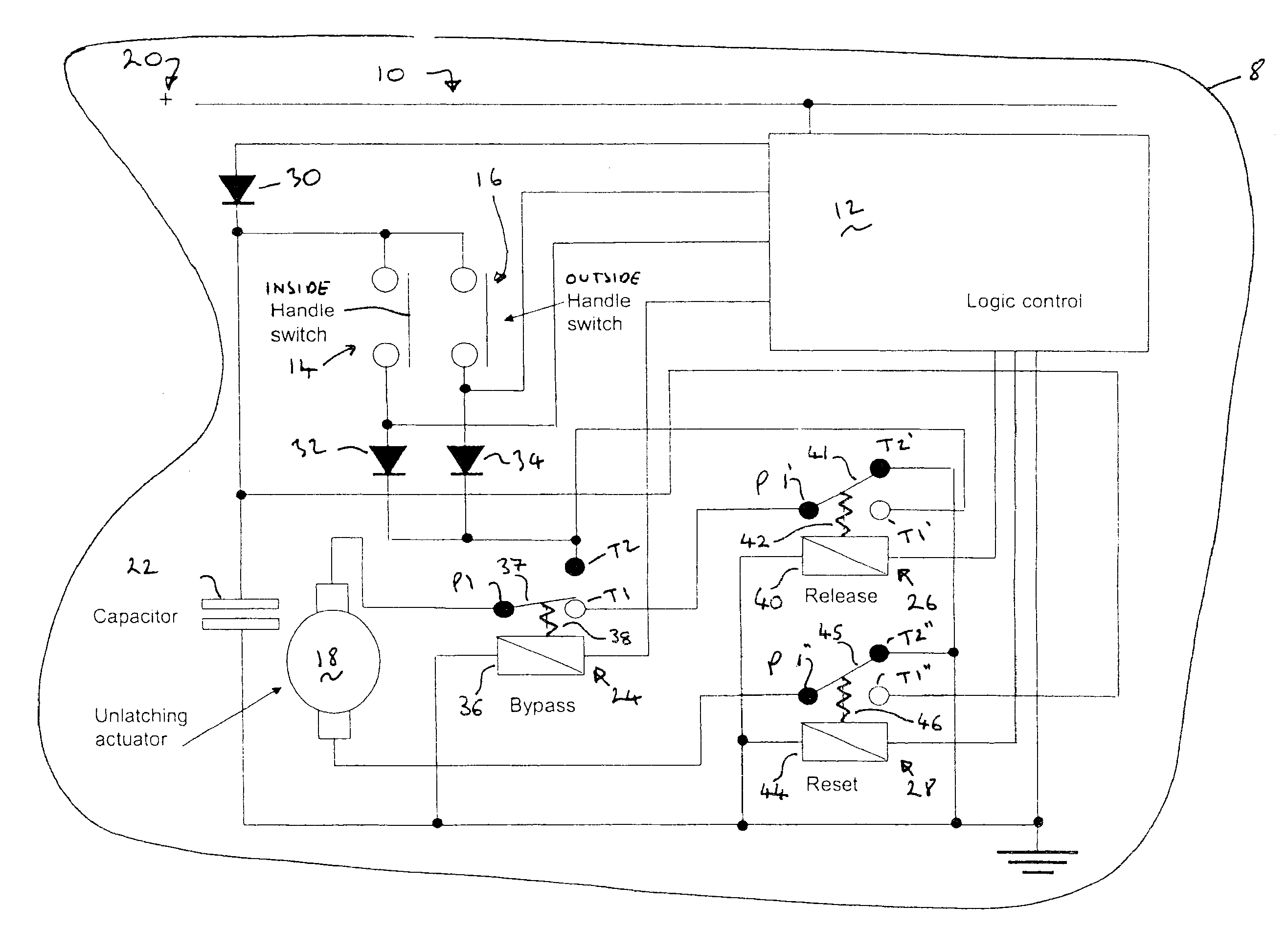
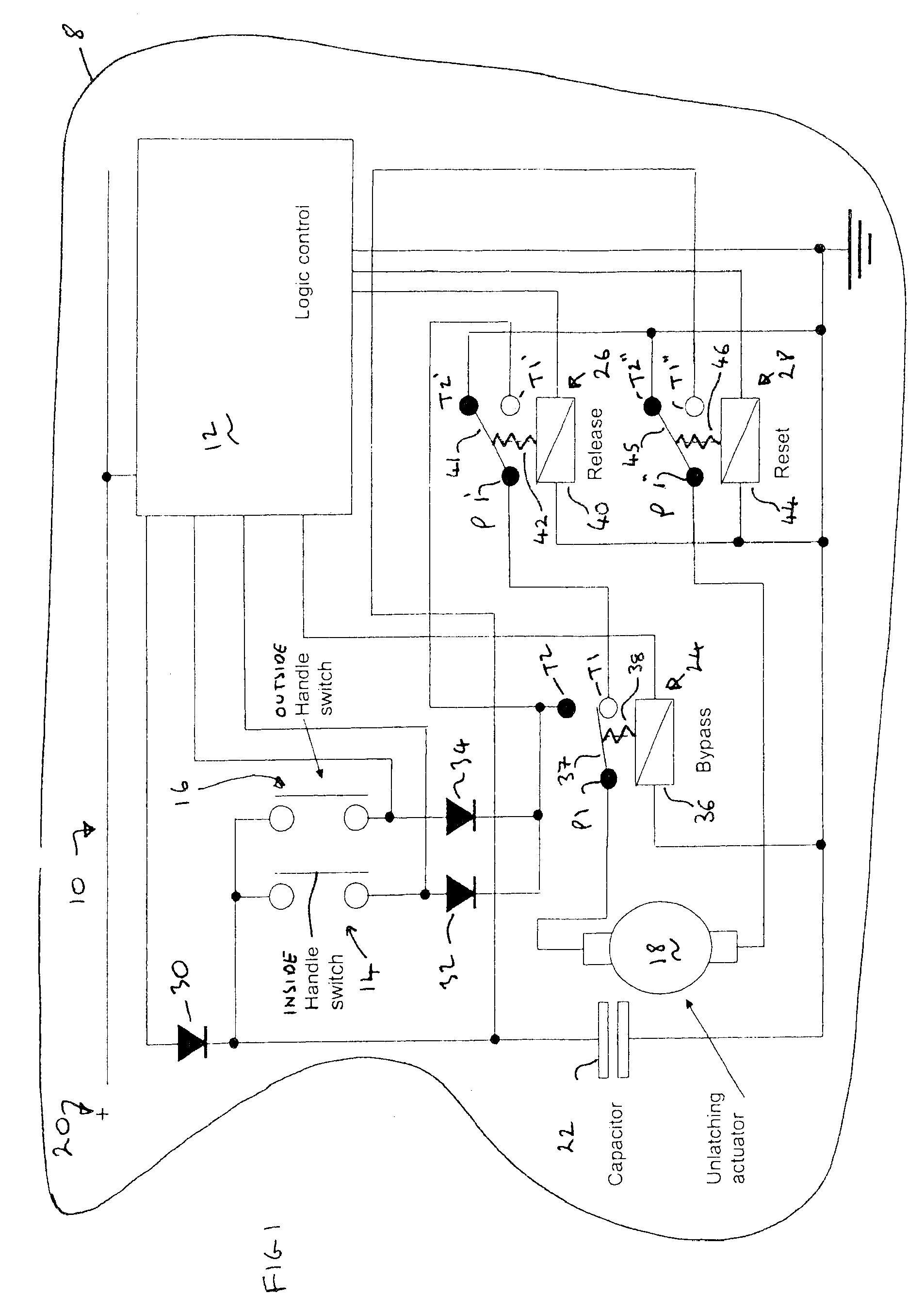
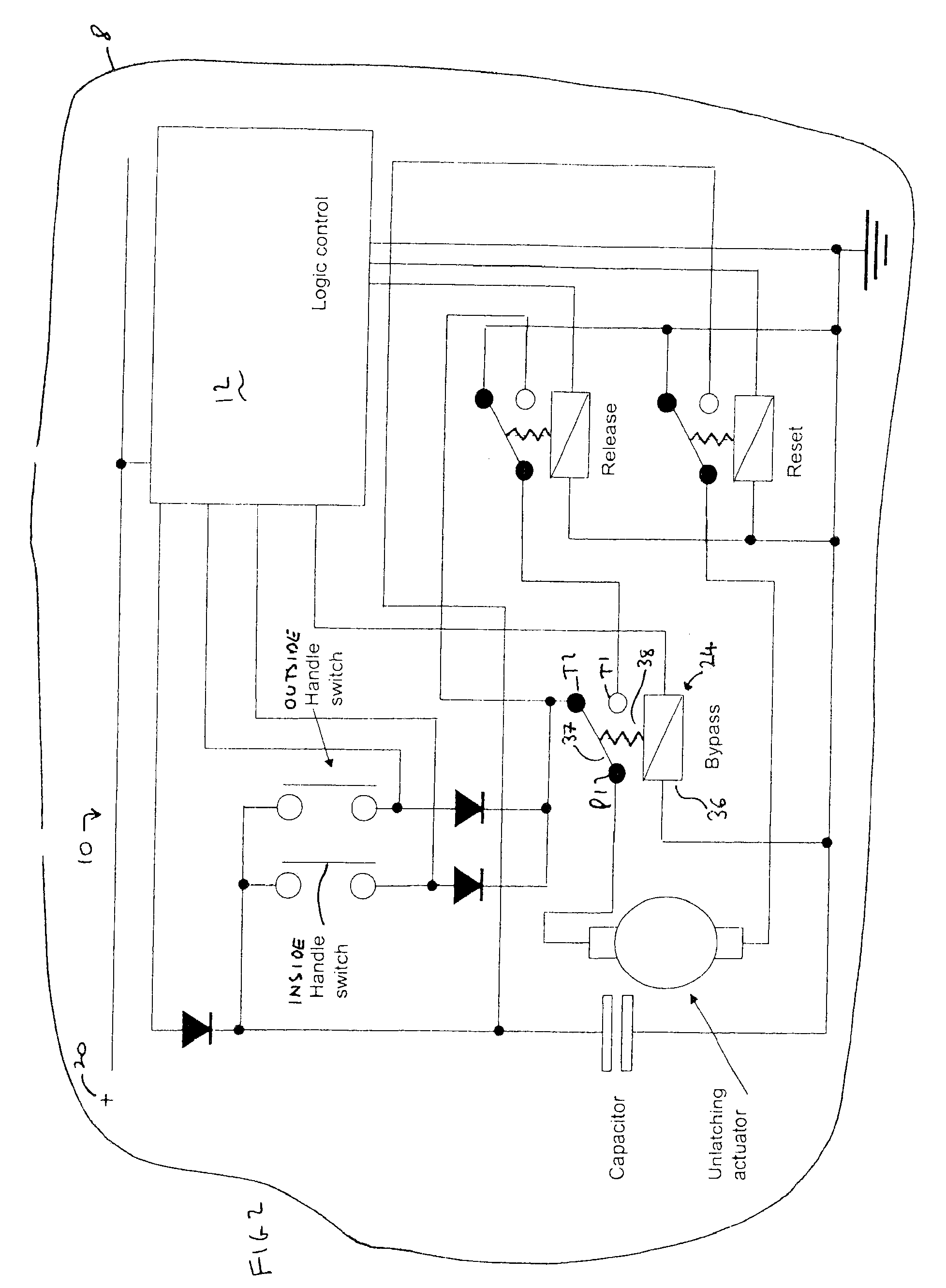
[0010]With reference to FIGS. 1 and 2, there is shown an electric circuit arrangement 10, the major components of which are a logic controller 12, an inside handle switch 14, an outside handle switch 16, an unlatching actuator 18, a primary power source 20, a secondary power source 22 in the form of a capacitor, a bypass switch 24, a release switch 26 and a reset switch 28. The components are mounted on a vehicle 8 (shown schematically).

[0011]The logic controller 12 controls the bypass switch 24, the release switch 26 and the reset switch 28 and receives signals from the inside handle switch 14 and the outside handle switch 16, as will be described below.

[0012]The inside handle switch 14 will typically be mounted within easy reach of a vehicle occupant when seated. The inside handle switch 14 may be mounted on the door adjacent to the seat or alternatively can be mounted on some fixed structure of the vehicle 8. The outside handle switch 16 will typically be mounted on or adjacent a...


PUM


Abstract

An electrical circuit arrangement includes an unlatching actuator, a primary power source and a secondary power source. The electrical circuit arrangement further includes an operator actuated switch and an electrically controlled bypass switch having an energized condition at which the bypass switch adopts a first switching configuration and a de-energized condition at which the bypass switch adopts a second switching configuration. The circuit has a first configuration in which the bypass switch is in the first switching configuration so that the primary power source, the operator actuated switch, the bypass switch and the unlatching actuator are configured so that actuation of the operator actuated switch causes the unlatching actuator to be energized by the primary power source. The circuit has a second configuration in which the bypass switch is in the second switching configuration so that the secondary power source, the operator actuated switch, the bypass switch and the unlatching actuator are configured so that actuation of the operator actuated switch causes the unlatching actuator to be energized by the secondary power source.

Description

REFERENCE TO RELATED APPLICATIONS[0001]This application claims priority to United Kingdom Patent Application GB 0612879.7 filed on Jun. 29, 2006.BACKGROUND OF THE INVENTION[0002]The present invention relates to an electric circuit arrangement for operating an unlatching actuator. The unlatching actuator may unlatch a door latch, in particular a vehicle door latch, more particularly a land vehicle door latch, such as a car passenger door.[0003]Vehicle door latches with an electric control are known. International patent application number PCT / CA2004 / 001958 shows an electronic latch arrangement in which power from a main power source is used to unlatch vehicle doors via an unlatching actuator. In the event that the main power source becomes disconnected from the unlatching actuator (such as following a vehicle crash), the power required for unlatching is drawn from a back-up battery contained within the circuit. The circuit further includes a bank of capacitors connected between the m...

Claims


Application Information

Patent Timeline
Patent Type & Authority Patents(United States)
IPC IPC(8): B60L1/00B60R25/00H02J9/00
CPCE05B81/76E05B81/54E05B81/82E05B81/86E05B77/30Y10T70/5889E05B77/28Y10T307/615E05B77/26
Inventor SPURR, NIGEL
Owner INTEVA PRODUCTS LLC
Why Eureka
Try Eureka