White balance control method, white balance control apparatus and image-taking apparatus
a control apparatus and white balance technology, applied in the direction of color television details, television systems, color signal processing circuits, etc., can solve the problems of color failure and inability to accurately detect the color of the light source, and achieve the effect of reducing color failur
- Summary
- Abstract
- Description
- Claims
- Application Information
AI Technical Summary
Benefits of technology
Problems solved by technology
Method used
Image
Examples
first embodiment
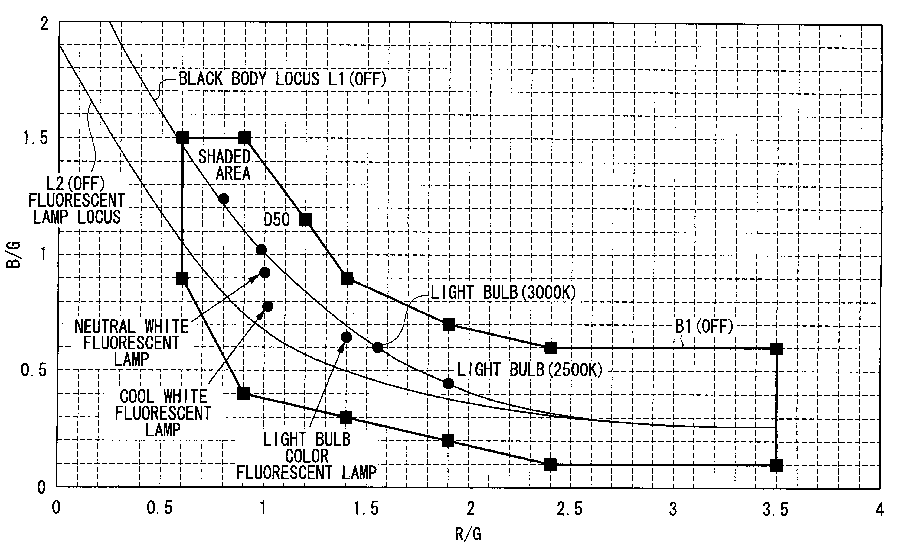
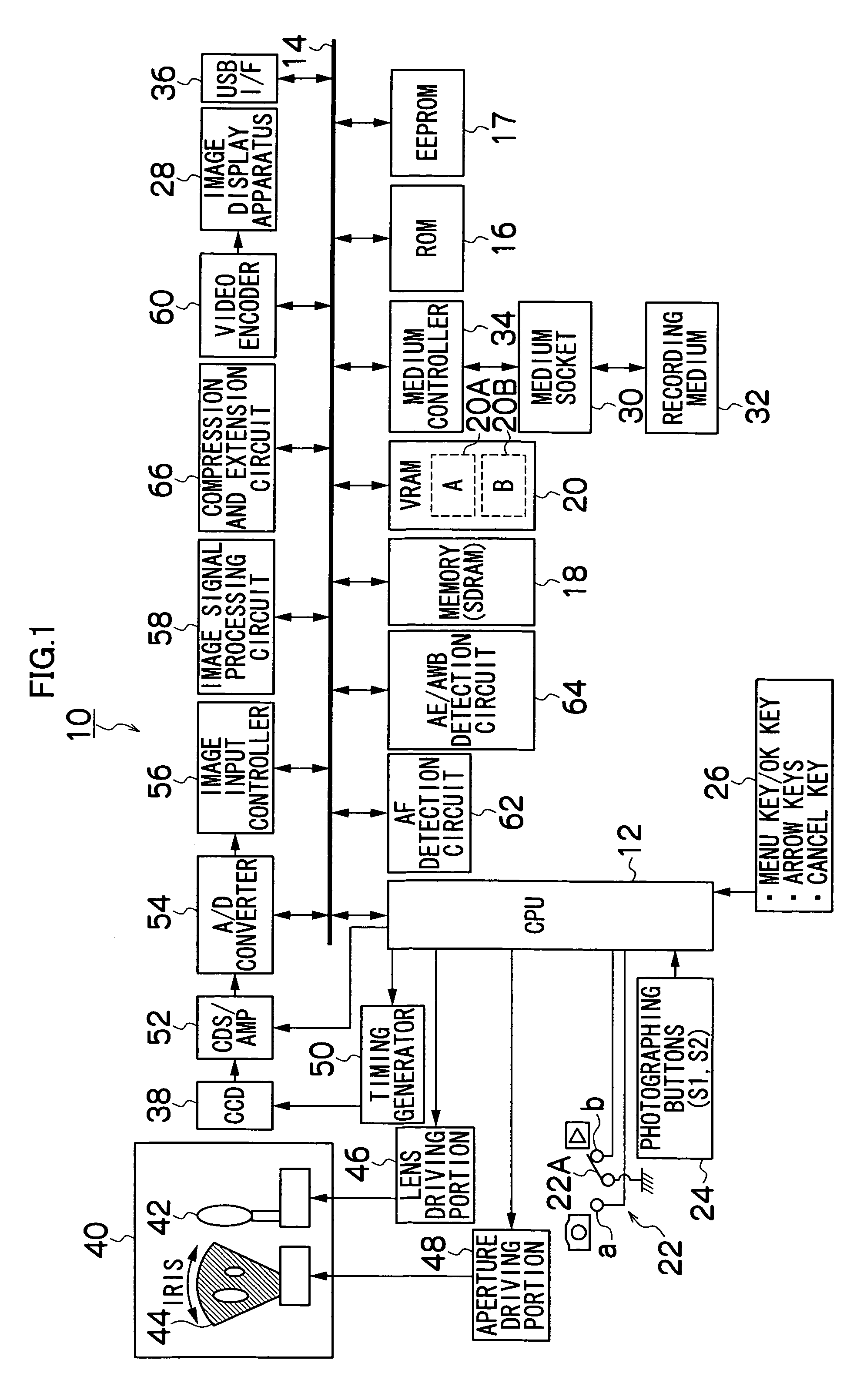
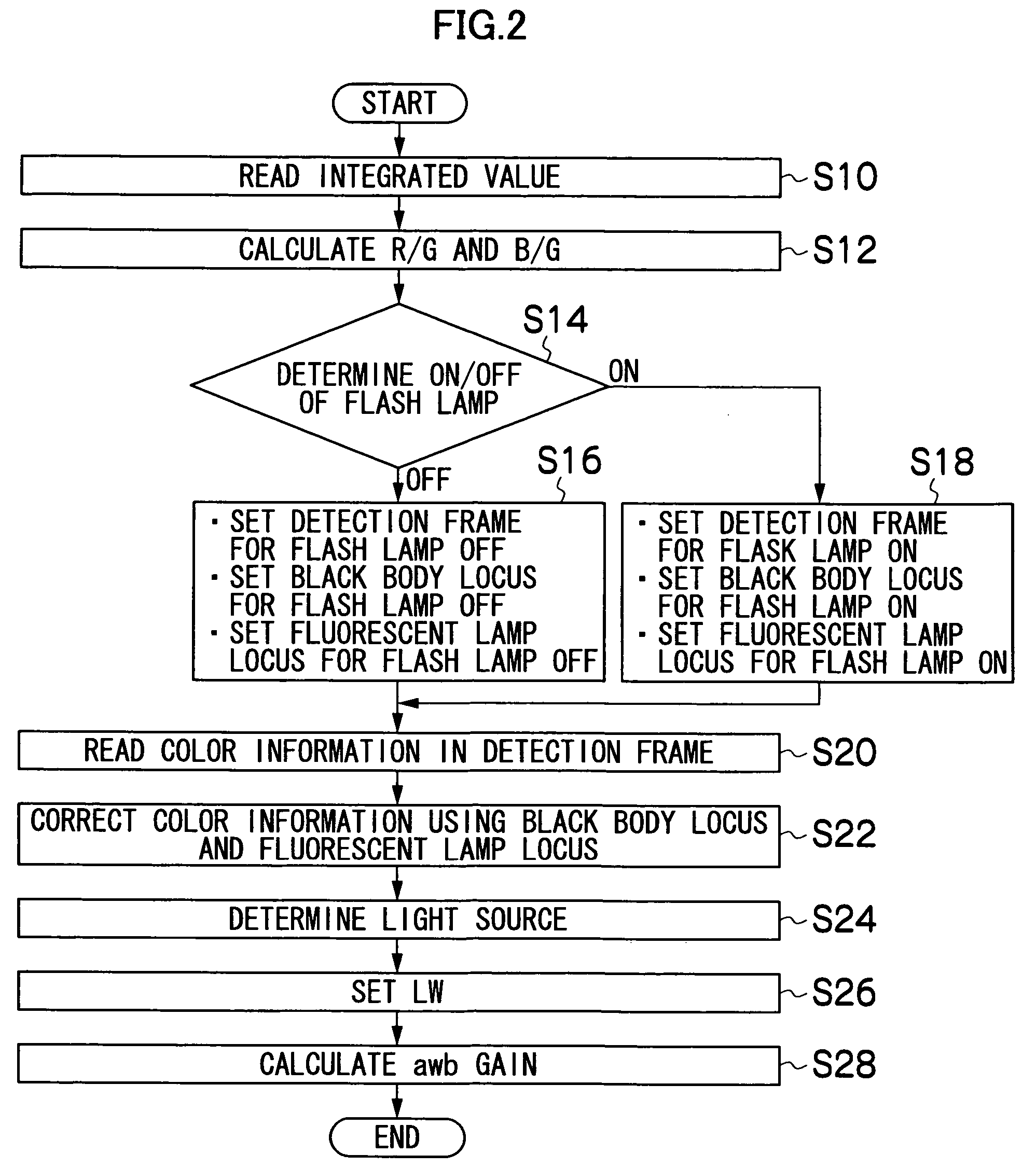
[0069]Next, the white balance control method according to the present invention will be described. FIG. 2 is a flowchart showing the white balance control method according to the present invention. First, the photographing button 24 is pushed to photograph the subject. The R, G and B signals obtained from the CCD 38 on the photographing are stored in the memory 18 once. And the R, G and B signals stored in the memory 18 are used to calculate the average integrated value of each color of the R, G and B signals for each of 64 divided areas which are one screen divided into 8×8 (step S10) so as to calculate the ratios of the average integrated values of the R, G and B signals (R / G and B / G) per divided area (step S12). It is possible, based on the R / G and B / G values, to represent color information on each of the 64 divided areas calculated in the step S12 as 64 points distributed on the color space of R / G and B / G axis coordinates (referred to as R / G and B / G color space in the following ...
second embodiment
[0095] the white balance correction value (white balance gain) is calculated by using the luminance weighting function according to the luminance value (S1 photometric value) of the image. Thus, it is possible to reduce the color failure when controlling the white balance.
[0096]Next, a third embodiment of the present invention will be described. According to the third embodiment, the light source detection values are calculated based on the weighted average of the distribution of the color information (the step S24 of FIG. 2 and step S54 of FIG. 9). If the R / G coordinate and B / G coordinate of the color distribution are xi and yi respectively, the weighted averages (Xave, Yave) of the color distribution are represented by the following formulas (25) and (26).
Xave=ΣixiWi / Σi Wi (25)
Yave=ΣiyiWi / Σi Wi (26)
FIG. 15 is a graph showing the weight Wi. In the R / G and B / G color space, the weight Wi related to the color information distributed above the black body locus changes according to th...
third embodiment
[0098]And the light source detection values (XLSC, YLSC) of the third embodiment are represented by the following formulas (28) and (29). The weight WLi is the same as that in the above-mentioned embodiment (formulas (4), (5) and FIG. 8).
XLSC=ΣixiWiWLi / Σi WiWLitm (28)
YLSC=ΣiyiWiWLi / Σi WiWLi (29)
[0099]Therefore, 100-percent complete correction gains are represented by the following formulas (30) to (32). And total gains are the same as those in the above-mentioned embodiment.
Gr=gri—t×Gd=Rd / XLSC (30)
Gg=Gd (31)
Gb=gbi—t×Gd=Bd / YLSC (32)
[0100]According to the third embodiment, it is possible to tone down the influence of the object color on the light source detection by increasing the weight Wi exerted on the color information close to the first and second light source loci (black body locus and fluorescent lamp locus).
PUM
 Abstract
Description
Claims
Application Information
 - R&D
- Intellectual Property
- Life Sciences
- Materials
- Tech Scout
- Unparalleled Data Quality
- Higher Quality Content
- 60% Fewer Hallucinations
Browse by: Latest US Patents, China's latest patents, Technical Efficacy Thesaurus, Application Domain, Technology Topic, Popular Technical Reports.
© 2025 PatSnap. All rights reserved.Legal|Privacy policy|Modern Slavery Act Transparency Statement|Sitemap|About US| Contact US: help@patsnap.com


