Image pickup apparatus and method of manufacturing thereof

a pickup apparatus and image technology, applied in the field of image pickup apparatus, can solve the problems of large number of components and increase in cos

Inactive Publication Date: 2010-01-05
PANASONIC CORP
View PDF9 Cites 20 Cited by
  • Summary
  • Abstract
  • Description
  • Claims
  • Application Information

AI Technical Summary

Benefits of technology

[0016]It is an object of the present invention to provide an image pickup apparatus that can be realized with a small number of components at low cost. It is another object of the invention to provide a method for assembling an image pickup apparatus that can be realized at low cost.
[0019]According to the present invention, it is possible to realize a low-cost image pickup apparatus with a small number of components.

Problems solved by technology

However, in the conventional configuration, the trim ring 101 is made up of the cover ring 102, the double-faced tape 103 and the holding ring 104, resulting in the problem of a large number of components and cost increase.

Method used


Image

  • Image pickup apparatus and method of manufacturing thereof
  • Image pickup apparatus and method of manufacturing thereof
  • Image pickup apparatus and method of manufacturing thereof

Examples


embodiment 1

[0038]In the following description, a digital still camera is described as one example of the image pickup apparatus.

[1. Configuration of Image Pickup Apparatus]

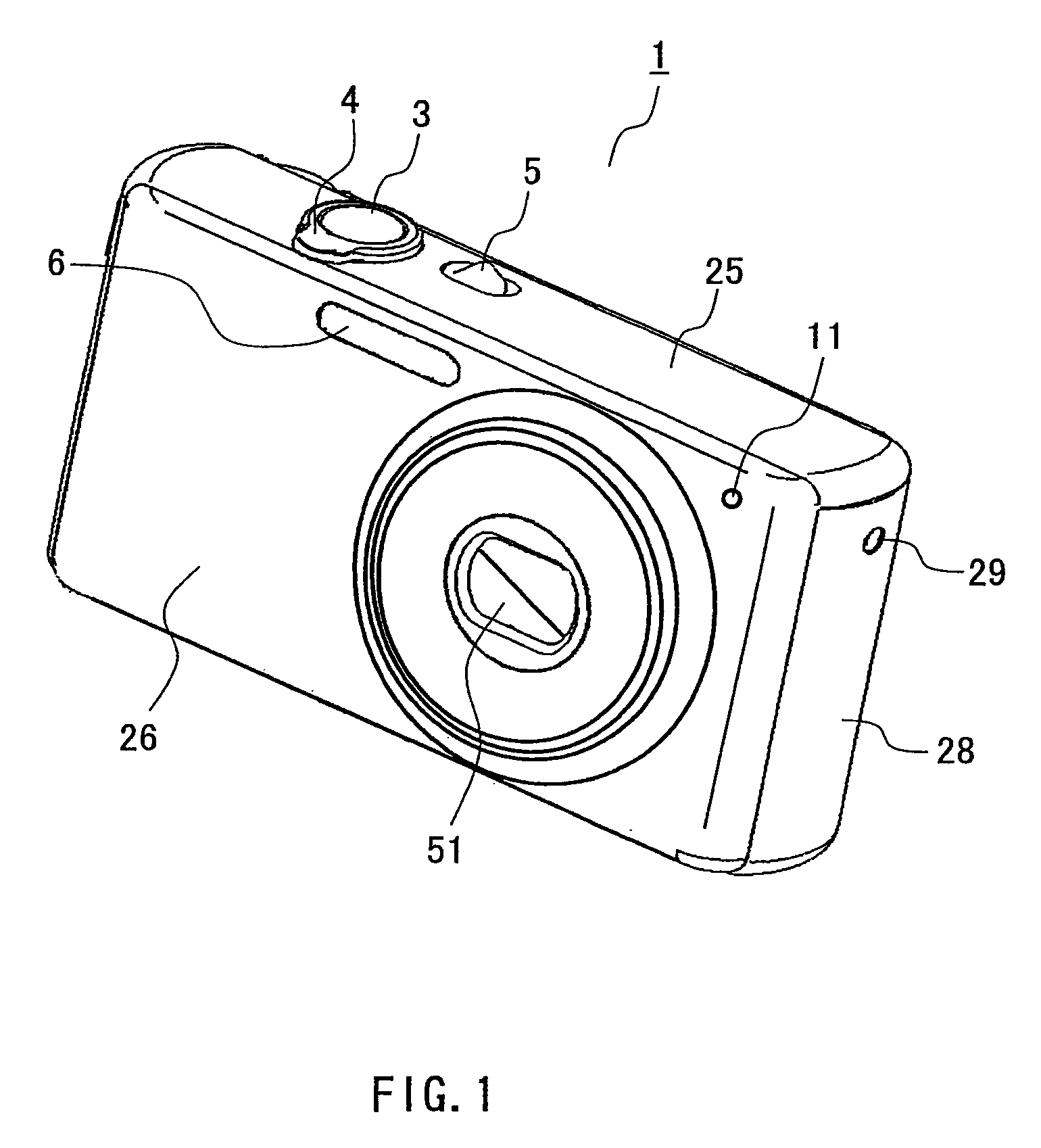
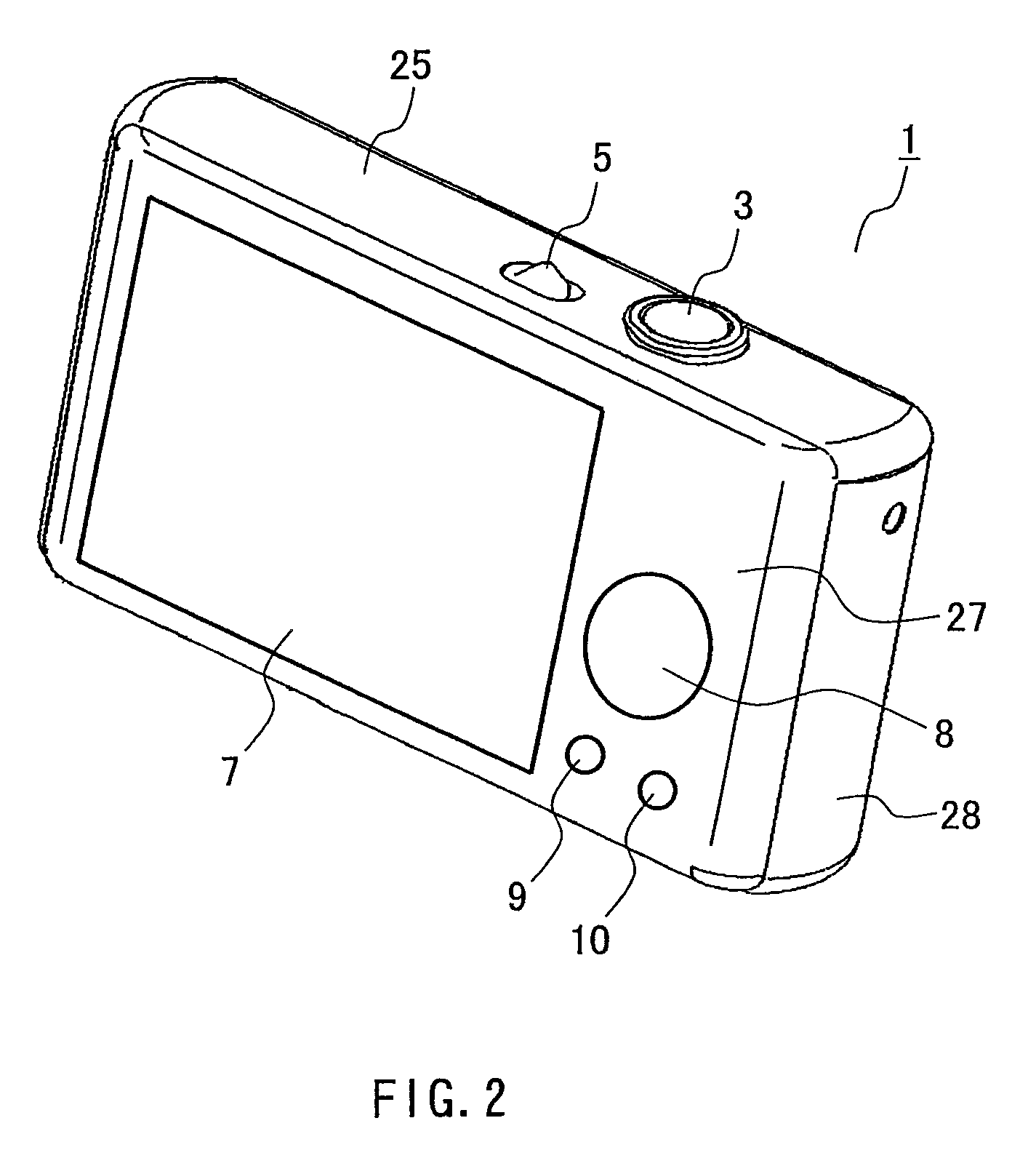
[0039]FIGS. 1 and 2 are perspective views showing the external configuration of an image pickup apparatus. FIG. 1 shows the surface of the image pickup apparatus on which a lens is disposed (hereinafter, referred to as “front surface”). FIG. 2 shows the surface of the image pickup apparatus on which a display portion is mounted (hereinafter, referred to as “rear surface”). It should be noted that FIGS. 1 and 2 show a schematic representation, and a portion of the configuration is omitted for convenience.

[0040]As shown in FIGS. 1 and 2, the image pickup apparatus 1 includes an image pickup portion 51, a release switch 3, a zoom switch 4, a power switch 5, a flash lamp 6, a display portion 7, a cursor key 8, buttons 9 and 10 and a light-emitting portion 11. The image pickup portion 51, the flash lamp 6 and the light-emitting p...


PUM


Abstract

An image pickup apparatus of the present invention is a portion of the image pickup portion is exposed on a first surface of the casing. The apparatus includes: a holding frame disposed on a second surface, which is the rear surface of the first surface of the casing, wherein the image pickup portion is held by the holding frame, and the holding frame is fixed to a third surface adjacent to the second surface. With this configuration, it is possible to reduce the number of components, and to eliminate the need for the step of attaching the double-faced tape, and the step of attaching the cover ring to the front panel.

Description

BACKGROUND OF THE INVENTION[0001]1. Field of the Invention[0002]The present invention relates to an image pickup apparatus, such as a digital still camera. The invention also relates to a method for assembling such an image pickup apparatus.[0003]2. Description of Related Art[0004]Recently, a higher resolution, as well as size and weight reduction has been achieved for image pickup apparatuses such as a digital still camera.[0005]FIG. 14 is a perspective view showing the external appearance of a conventional image pickup apparatus.[0006]As shown in FIG. 14, the conventional image pickup apparatus 100 contains an image pickup portion 105 containing a lens, an image pickup element and so on and being partially exposed outside. A trim ring 101 is disposed around the image pickup portion 105. The image pickup portion 105 is fixed to a front panel of the image pickup apparatus 100 with a plurality of screws 106 (see FIG. 13).[0007]FIG. 15 is an exploded perspective view showing the confi...

Claims


Application Information

Patent Timeline
Patent Type & Authority Patents(United States)
IPC IPC(8): H04N5/225G03B17/02
CPCG03B17/02H04N5/2252H04N23/51
Inventor SAIKI, JUNNAGASHIMA, MIYUKI
Owner PANASONIC CORP
Why Eureka
Try Eureka