Navigational device for mounting on a support pillar of a vehicle and a method for doing same

Active Publication Date: 2010-01-19
GARMIN
View PDF125 Cites 78 Cited by
  • Summary
  • Abstract
  • Description
  • Claims
  • Application Information

AI Technical Summary

Benefits of technology

[0010]The present invention solves the above-described problems and provides a distinct advance in the art of navigational devices. More particularly, the present invention provides a navigational device that may be removably or permanently mounted in a vehicle not designed to receive a navigational device, without requiring use of a dashboard mount.

Problems solved by technology

In other embodiments, the navigational device is a conventional, portable navigational device and thus, is not particularly sized and configured to fit within an existing location in the vehicle.

Method used


Image

  • Navigational device for mounting on a support pillar of a vehicle and a method for doing same
  • Navigational device for mounting on a support pillar of a vehicle and a method for doing same
  • Navigational device for mounting on a support pillar of a vehicle and a method for doing same

Examples


first embodiment

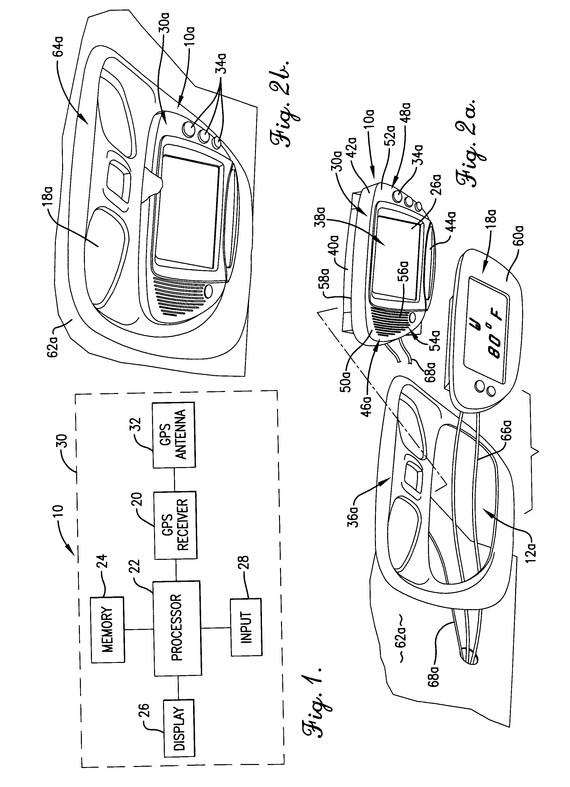
[0071]As illustrated in FIGS. 6 and 7, the housing 30b is preferably approximately six inches wide, four inches high, and five inches deep, although the width may range between two inches and twelve inches, the height may range between two inches and twelve inches, and the depth may range between two inches and twelve inches. Similar to the first embodiment, the housing 30b includes a front, frame-shaped section 38b and an attached rear, box-shaped section 40b. The front section 38b includes upper and lower walls 42b,44b and left and right side walls 46b,48b which together define an enclosed area for receiving a display 26b. Control buttons 34b are positioned on the lower wall 44b. The left and right side walls 46b,48b are generally arcuate when viewed from a side and preferably project outwards from the display 26b so as to match the contours of the open port 12b.

[0072]The rear section 40b is attached to a rear face 58b of the front section 38b and houses a navigation component (n...

eleventh embodiment

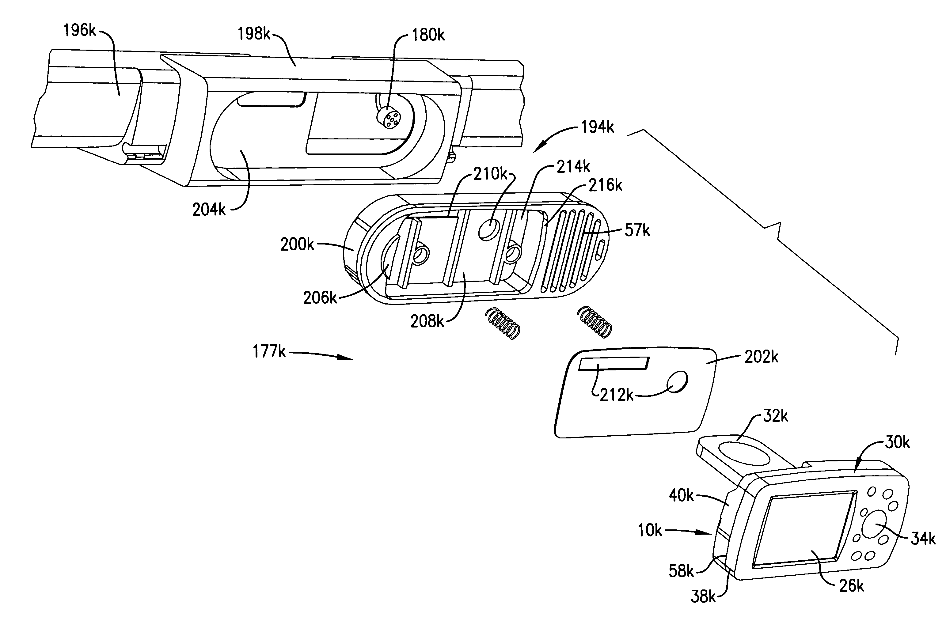
[0102]In an eleventh preferred embodiment of the present invention, illustrated in FIGS. 19-22, a navigation assembly 177k for locating a conventional, portable navigational device 10k in a vehicle is provided. The eleventh preferred embodiment is substantially similar to the sixth preferred embodiment in that the eleventh preferred embodiment provides a new location for mounting the navigational device 10k in the vehicle, wherein the new location was not formed during manufacture of the vehicle and does not result from removal of a non-navigational component 18. Unlike the sixth preferred embodiment, however, the eleventh preferred embodiment uses the conventional, portable navigational device 10k that is not particularly sized and configured to the contours and dimensions of an existing port 12 or empty recess 14 in the vehicle. Instead, the eleventh embodiment creates a receptacle that is sized and configured to receive a conventionally sized navigational device. An example of th...


PUM


Abstract

A navigation assembly (177k) for mounting a conventional, portable navigational device (10k) in a vehicle not originally equipped with navigational capabilities is provided. The navigation assembly (177k) comprises the navigational device (10k) and a mounting assembly (194k). Trim (196k) covering a support pillar (98k) of the vehicle and installed during manufacture of the vehicle is replaced with substantially similar trim (196k) having the mounting assembly (194k) mounted thereto or integrally formed therewith. The mounting assembly (194k) comprises a base (198k), a docking station (200k), and a retractable face plate (202k). The base (198k) of the mounting assembly (194k) is secured to the trim (196k) and includes a cut-out (204k) in which the docking station (200k) may be mounted. The docking station (200k) also includes a cut-out (208k) sized and configured to receive the navigational device (10k). The retractable face plate (202k) covers the cut-out (208k) in the docking station (200k) and is retracted in the rearward position when the navigational device (10k) is mounted in the docking station (200k) and is retracted in the forward position when the navigational device (10k) is not mounted in the docking station (200k).

Description

RELATED APPLICATIONS[0001]The present application is a continuation-in-part and claims priority benefit, with regard to all common subject matter, of U.S. application Ser. No. 10 / 411,821, filed Apr. 11, 2003, and titled “A NAVIGATIONAL DEVICE FOR INSTALLATION IN A VEHICLE AND A METHOD FOR DOING SAME,” which is a continuation-in-part of U.S. application Ser. No. 10 / 397,662, filed Mar. 26, 2003, and titled “A NAVIGATIONAL DEVICE FOR INSTALLATION IN A VEHICLE AND A METHOD FOR DOING SAME.” This application is also co-pending with U.S. Application Ser. No. 10 / 663,044, being filed concurrently on Sep. 13, 2003, and titled “A NAVIGATIONAL DEVICE FOR INSTALLATION IN A VEHICLE AND A METHOD FOR DOING SAME.” All of the above-identified earlier-filed and co-pending applications are hereby incorporated by reference into the present application.BACKGROUND OF THE INVENTION[0002]1. Field of the Invention[0003]The present invention relates to navigational devices. More particularly, the invention re...

Claims


Application Information

Patent Timeline
IPC IPC(8): H05K5/02G01C21/00
CPCG01C21/26G01C21/265
Inventor LAVERICK, DAVID J.SCHOENFISH, BRIAN G.
Owner GARMIN
Why Eureka
Try Eureka