Supercharge Your Innovation With Domain-Expert AI Agents!

Flexible JTAG architecture

a flexible, jtag technology, applied in the direction of driving belts, mechanical equipment, instruments, etc., can solve the problems of limiting applications, components unnecessary to applications may run at slower speeds than the necessary components, and one standard chain structure may not meet all needs, etc., to achieve the effect of more efficien

Inactive Publication Date: 2010-01-19
RPX CORP
View PDF5 Cites 0 Cited by
  • Summary
  • Abstract
  • Description
  • Claims
  • Application Information

AI Technical Summary

Benefits of technology

[0008]Embodiments of the present invention make more efficient use of JTAG chains by enabling a selection between more than one JTAG chain of different lengths and allowing more than one device to control a JTAG chain.

Problems solved by technology

One of the challenges in creating a JTAG architecture is that the preferred length of the chain and its starting and stopping point is different depending on the application.
Using a long chain that includes all of the JTAG components may limit the application by the restrictions of the components unnecessary to the application.
For example, a component unnecessary to the application may run at slower speed than the necessary components or may be corrupted.
Furthermore, one standard chain structure may not satisfy all needs.
In particular, using only one chain may not be the better option for the different functions that can be performed.

Method used


Image

  • Flexible JTAG architecture
  • Flexible JTAG architecture
  • Flexible JTAG architecture

Examples


Embodiment Construction

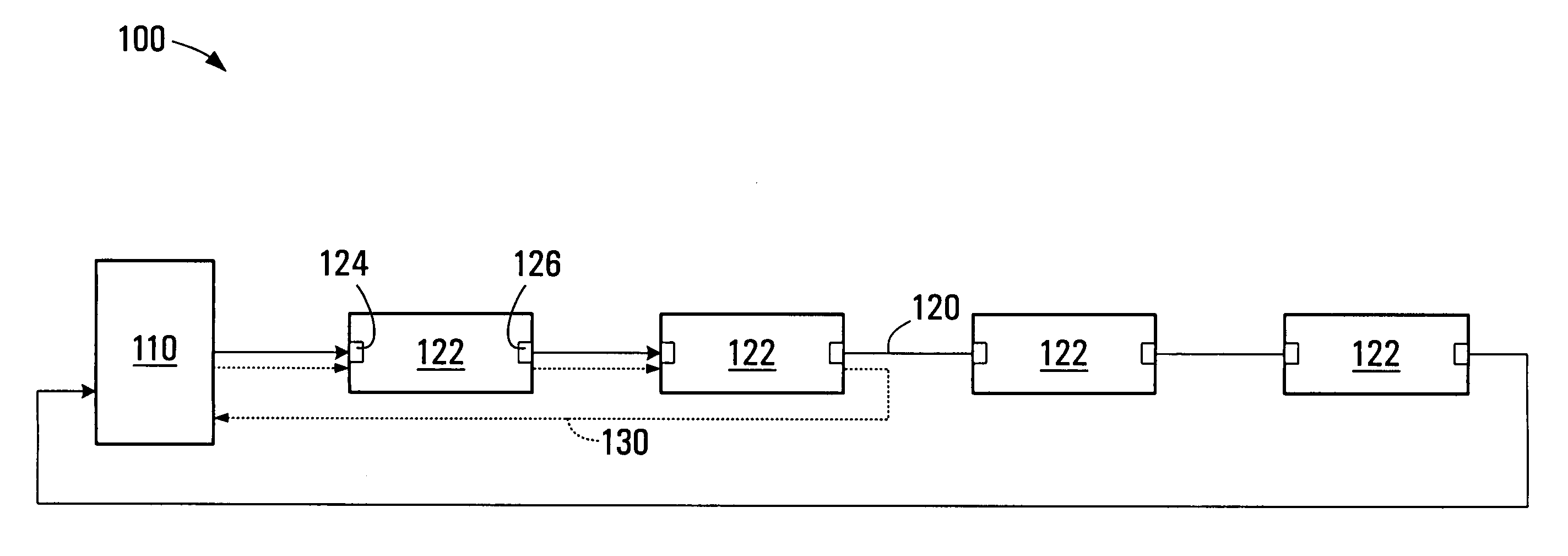
[0017]Referring to FIG. 1, one embodiment of the present invention is a circuit 100 comprising two or more chains 120 and 130 and a selector 110 for selecting one of the chains 120 or 130 over which to send data. While FIG. 1 depicts two chains, there may be more than two chains in other embodiments of the invention. Each chain 120 and 130 comprises a plurality of components 122. The components 122 of each chain 120 and 130 are serially connected within the chain by designated pins, the pins being designated for data for one or more specific purposes. For example, the components 122 receive data at pin 124 and output the data at pin 126 to the next component. The components of the chain 130 include two of the components of the chain 120. In FIG. 1, the chain 130 is a subset of the chain 120, although, other chains may exist that are not subsets of each other. Non-limiting examples of purposes for which the designated pins may be used are combinational testing, interconnect testing, ...


PUM


Abstract

A circuit comprises two or more chains of components, each chain comprising a plurality of components serially connected by designated pins on each component and at least one chain including one or more components of another chain, the designated pins being designated for data for one or more specific purposes. A selector is included for selecting one chain from the two or more chains over which to data is to be sent. Another circuit comprises a chain of components serially connected by designated pins on each component, and two or more controllers, each controller capable of controlling the chain for one or more of the specific purposes. A wiring board for implementing the circuit is also provided.

Description

FIELD OF THE INVENTION[0001]The present invention relates to a selector for selecting one of a plurality of chains of components, a circuit comprising the selector and chains, and a wiring board for implementing the circuit.BACKGROUND[0002]Existing networking equipment cards have components that are JTAG (Joint Test Group Action Group) compliant, i.e. meet the requirements of IEEE Standard 1149.1. There are many uses for the chain of components created when JTAG compliant components are assembled together. For example, they can be used for programming devices such as Lattice clock drivers; programming serial EEPROM (Electrically Erasable Programmable Read-Only Memory) and FPGAs (Field Programmable Gate Arrays), both during manufacturing and while in service; CT (Combinational Testing) and interconnect testing during manufacturing; and ILA (Integrated Logic Analyzer) debug access to FPGAs.[0003]One of the challenges in creating a JTAG architecture is that the preferred length of the ...

Claims


Application Information

Patent Timeline
Patent Type & Authority Patents(United States)
IPC IPC(8): G01R31/28
CPCG01R31/318536
Inventor MADSEN, JOHNPIKE, DIONGRIEVE, RICHARD
Owner RPX CORP
Features
  • R&D
  • Intellectual Property
  • Life Sciences
  • Materials
  • Tech Scout
  • Unparalleled Data Quality
  • Higher Quality Content
  • 60% Fewer Hallucinations
Learn More