Lock ring for a watthour meter application

a technology of watthour meters and lock rings, which is applied in the direction of carpet fasteners, locking devices, instruments, etc., can solve the problems of difficult use of lock pins lp and lock caps lc, poor safety, and inability to use them, so as to facilitate the bending of the heavier gage rings, reduce manufacturing costs, and high security

Inactive Publication Date: 2010-01-26
E J BROOKS
View PDF60 Cites 18 Cited by
  • Summary
  • Abstract
  • Description
  • Claims
  • Application Information

AI Technical Summary

Benefits of technology

[0021]The lock ring disclosed herein provides a high level of security to resist tampering with the lock ring in an attempt to obtain unauthorized access to non-metered and power in the meter socket. The lock ring can be manufactured of thinner gage material than previous high security lock rings which receive a barrel lock thereby reducing manufacturing costs since the ring can be manufactured in a single machine rather than in multiple machines. The lock ring also eliminates the need for cutouts or scallops in one of the side walls of the ring which are required to facilitate bending of the heavier gage rings used in the past. This eliminates another tampering point since the present lock ring cannot be disengaged from the meter mounting surfaces through a threading movement.
[0022]Uniquely, the lock mechanism employed on the lock ring accommodates the lock pin in one of a plurality of variably selectable positions thereby enabling the circumference of the lock ring to be varied to accommodate varying circumference meter mounting flanges while enabling the lock ring to be securely and non-movably mounted about the mounting flanges again eliminating one potential tampering point on the meter.

Problems solved by technology

However, this prior art lock ring still has several deficiencies.
Secondly, use of this lock pin LP and lock cap LC is difficult since the installer must hold the ends of the lock ring LR tightly about the mating mounting flanges, insert the lock pin LP through the aligned apertures in the ends of the lock ring LR while holding the lock cap LC in a position to receive the shank and lock balls LB of the lock pin LP.
This assembly process is awkward at best.

Method used


Image

  • Lock ring for a watthour meter application
  • Lock ring for a watthour meter application
  • Lock ring for a watthour meter application

Examples


Embodiment Construction

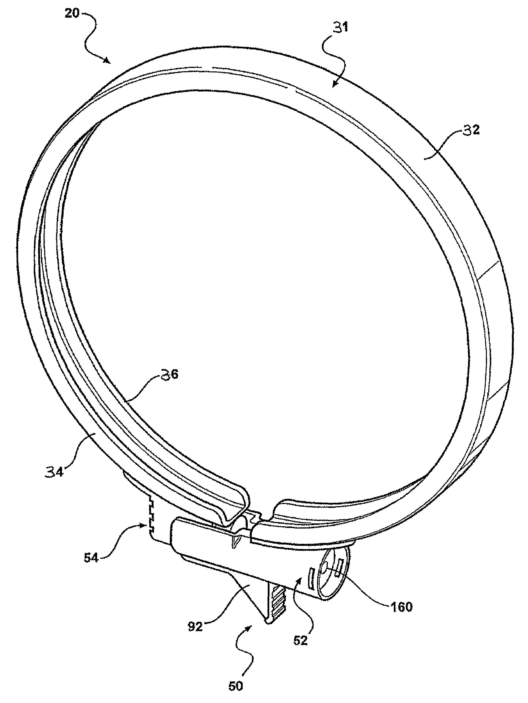
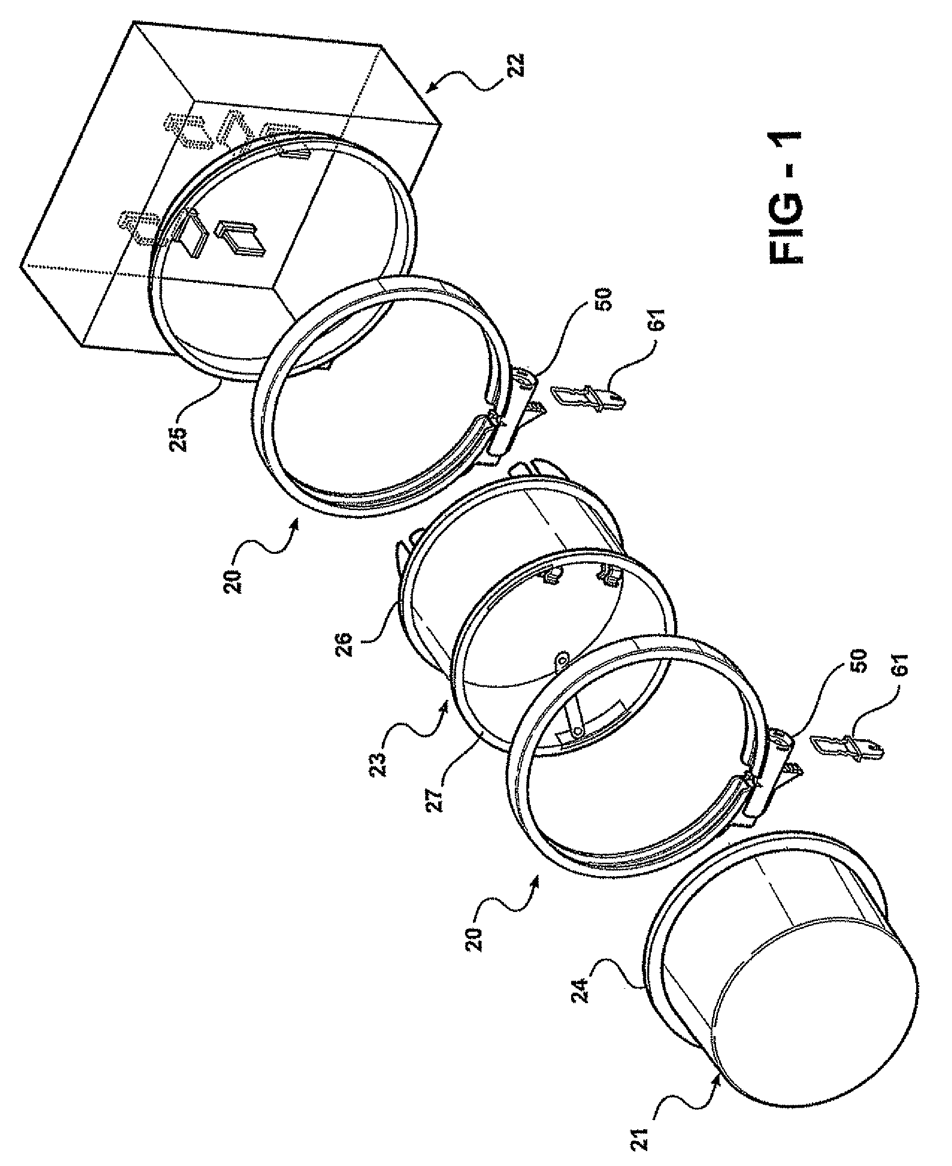
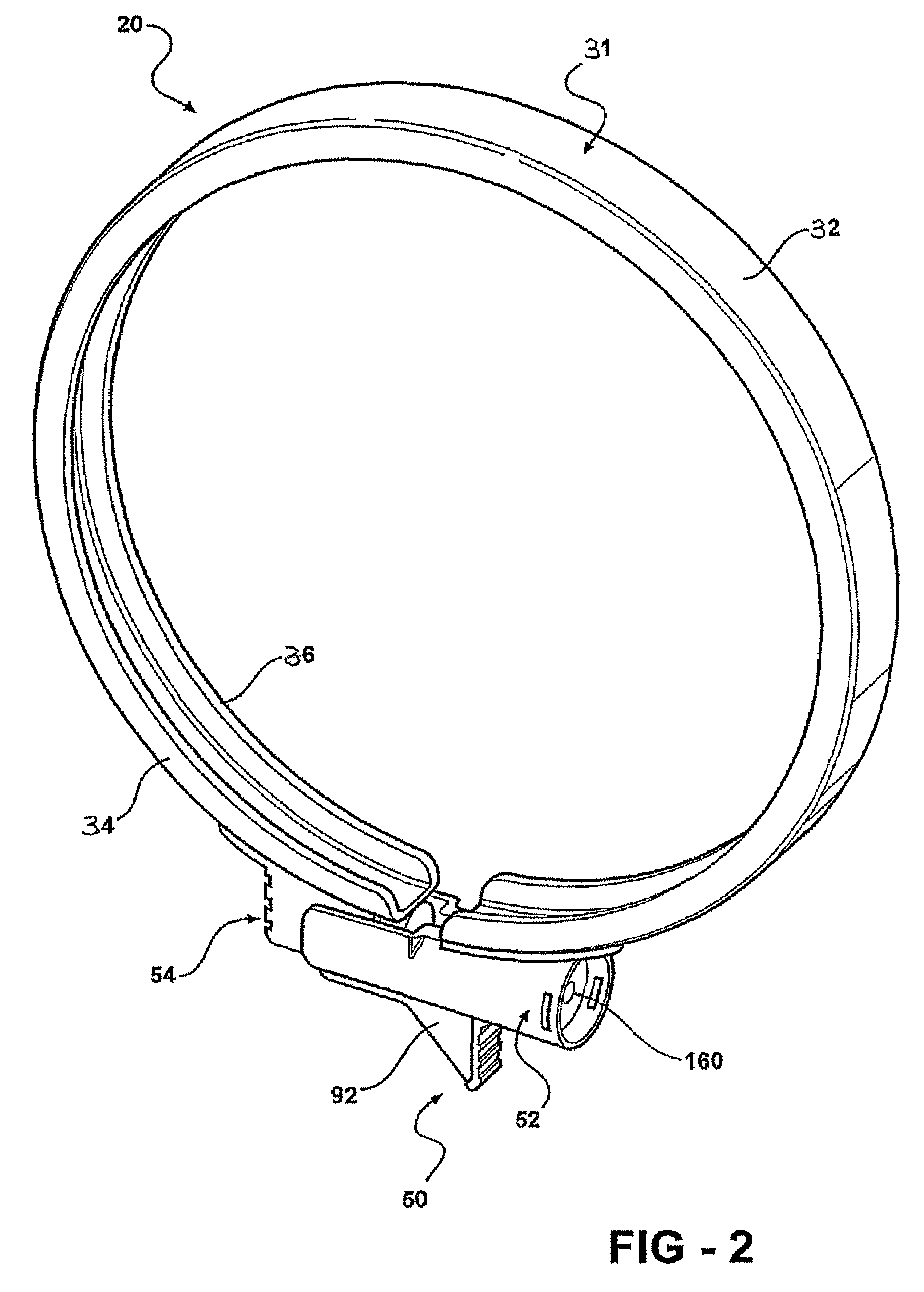
[0035]The present invention, as shown in FIGS. 1-10 is a lock ring 20 which is used to releasably mount a conventional electric watthour meter 21, blank cover, or a simulated meter on a meter socket 22 or watthour meter socket adapter 23. The lock ring 20 may also be employed to releasably mount a watthour meter socket adapter 23 on a watthour meter socket 22.

[0036]As is conventional, the electric watthour meter 21, the watthour meter adapter 23, and the watthour meter socket 22 are provided with a mating mounting flanges which abut each other to form an annular surface when, for example, a watthour meter 21 is mounted in a watthour meter socket 22. The watthour meter 21 has a base, ring-shaped mounting flange 24 which is engagable with a similar mounting flange 25 on the cover of the meter socket 22 and / or with a mounting flange 27 on the meter socket adapter 23. A base mounting flange 26 on the meter socket adapter 23 is engagable with the flange 25 on the cover of the meter socke...


PUM


Abstract

A lock ring for use in mounting a watthour meter, meter socket enclosure cover or a watthour meter socket adapter to each other. The lock ring includes a ring member and a housing carried on the first and second ends of the ring member. The housing may be separate housings carried on the first and second ends of the ring member. A lock is insertable into mated first and second housing members in one of a plurality of variably selectable positions that vary the circumference of the ring member to accommodate varied circumferences of watthour meters, meter socket adapters and meter socket enclosure cover mounting rings. Finger grips are formed on the housing members to facilitate closure of the housing. A plurality of axially spaced grooves are formed in one of the members for receiving lock members carried by the lock.

Description

BACKGROUND[0001]The present invention relates, in general, to lock or sealing rings for mounting watthour meters on meter enclosures and, more particularly, to lock or sealing rings using barrel locks.[0002]In the electric utility industry, watthour meters are employed to measure electrical power consumption at a residential or commercial building establishment. A cabinet is typically mounted on an outside wall of the residence or building and contains a meter socket having pairs of line and load contacts which are connected to electric power line conductors extending from the utility power network and electric load conductors connected to the residential or building establishment power distribution network. The contacts receive blade terminals on a plug-in watthour meter to complete an electric circuit through the meter between the line and load terminals mounted in the cabinet for the measurement of electrical power consumption.[0003]Lock rings are commonly employed with ring-styl...

Claims


Application Information

Patent Timeline
Patent Type & Authority Patents(United States)
IPC IPC(8): B65D55/14
CPCG01R11/04Y10S292/60Y10T70/5566Y10T292/205Y10T70/443Y10T70/8838Y10T70/7751
Inventor ROBINSON, DARRELL
Owner E J BROOKS
Why Eureka
Try Eureka