Closure cap for a bottle with controlled opening

Active Publication Date: 2010-01-26
PLASTOHM SA
View PDF12 Cites 12 Cited by
  • Summary
  • Abstract
  • Description
  • Claims
  • Application Information

AI Technical Summary

Benefits of technology

[0013]In this way, opening of the shut-off flap takes place independently of the force required to unlock the locking system and makes it possible to obtain accompaniment for opening, without intervention on the part of the user, and always with the same force.

Problems solved by technology

According to a first phase of the inventive approach, due consideration was given to the fact that the locking of the shut-off flap on the stopper was achieved by the pressing of the shut-off pip into the pouring hole of the stopper, or by any other means, but that the problem with opening arose after the travel of disengaging the said pip from the hole had been completed.

Method used


Image

  • Closure cap for a bottle with controlled opening
  • Closure cap for a bottle with controlled opening
  • Closure cap for a bottle with controlled opening

Examples


first embodiment

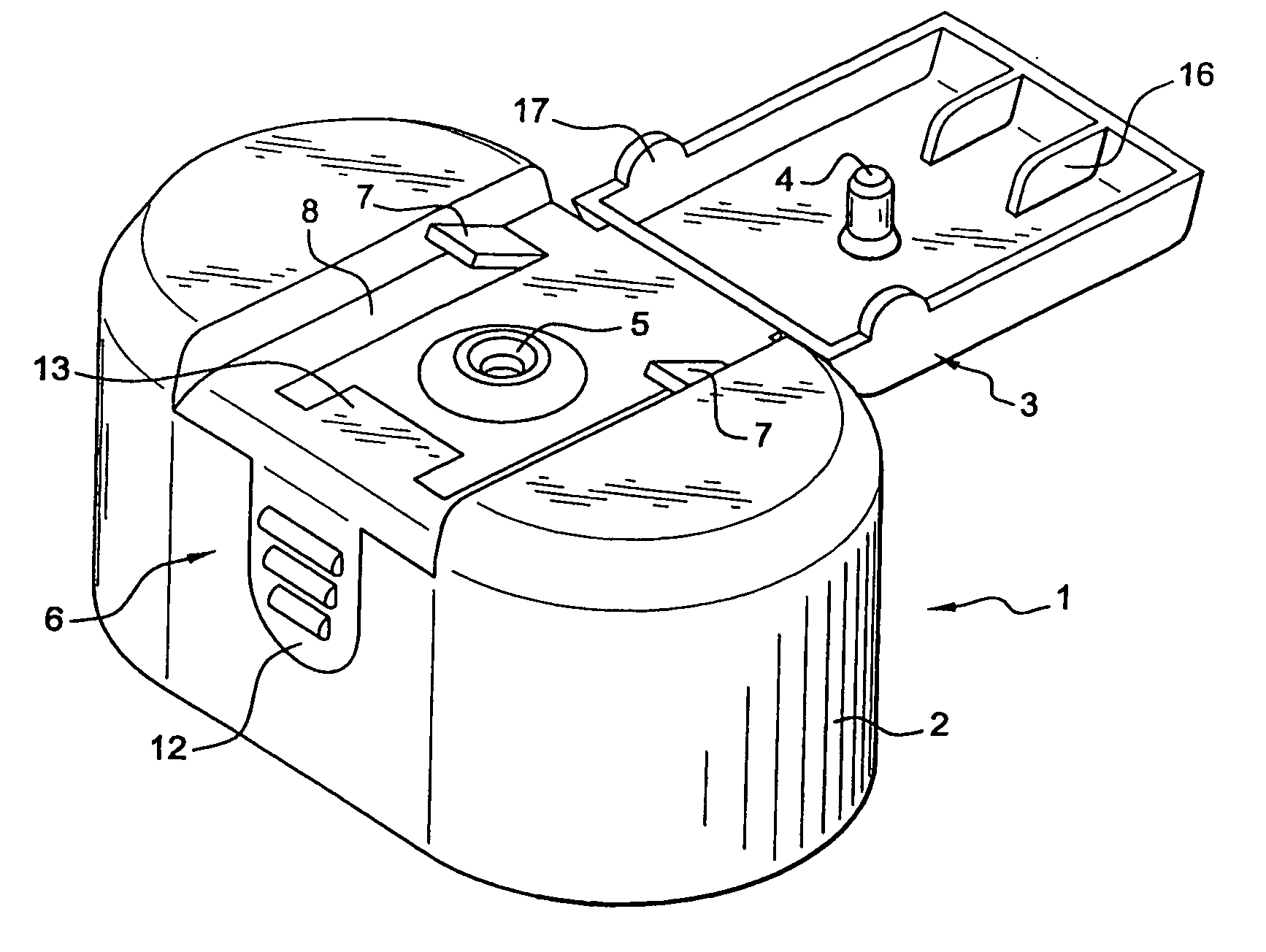
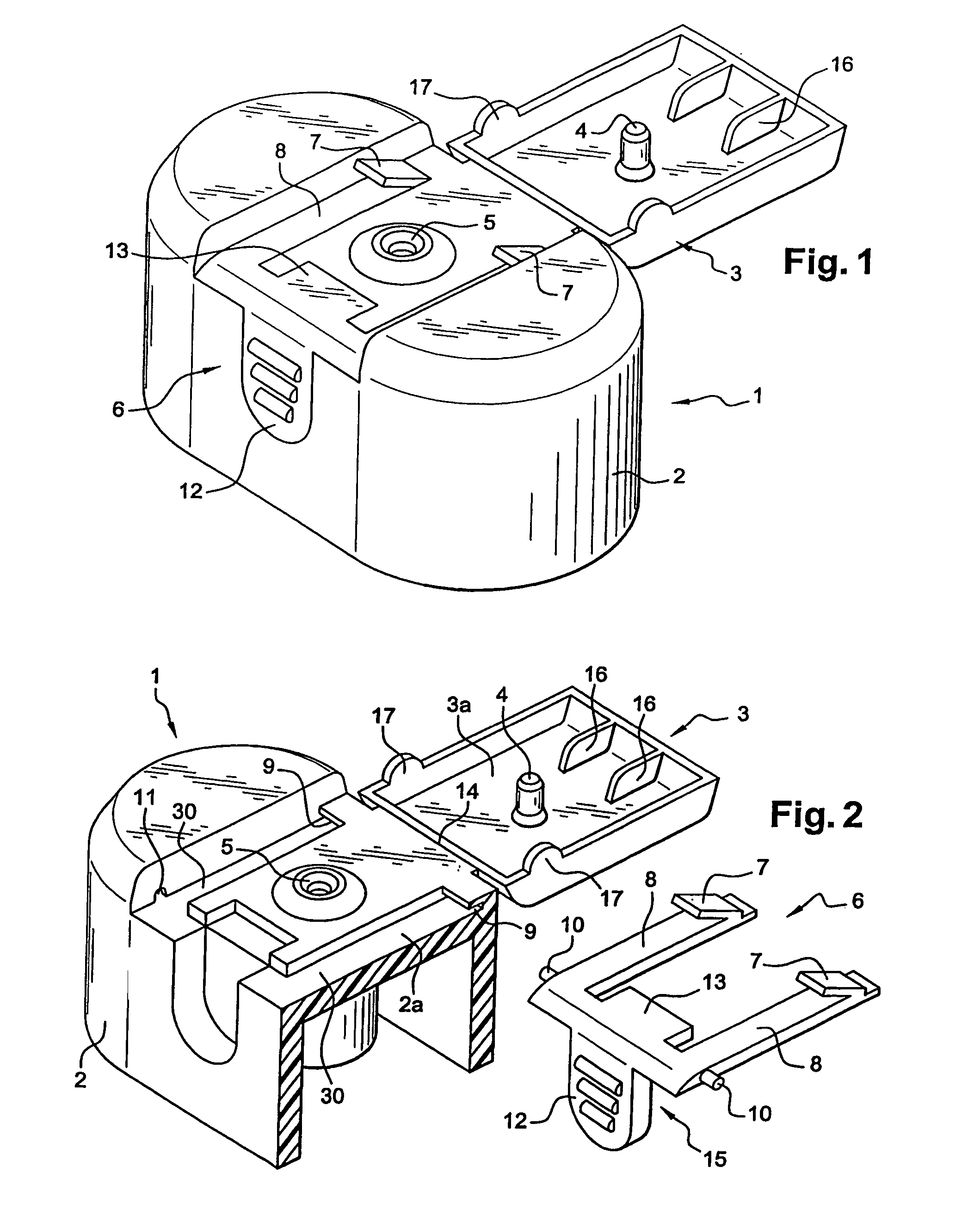
[0022] the means 6 for the controlled opening of the shut-off flap 3 consist of an energy-storing elastic member 7 inserted between an upper part 2a of the stopper 2 and a lower part of the shut-off flap 3 facing one another in closure, so as to keep said member under permanent compression in this position.

[0023]More specifically, the energy-storing elastic member 6 consists of two spring leaves 7 that are elastically deformable in one of their free parts, facing upwards and secured to two arms 8, one of the respective ends of which is immobilized in mortises 9 formed on the upper face 2a of the stopper 2. Each of the other ends of the arms 8 is equipped with a lateral pivot 10 able to fit in corresponding respective housings 11 formed facing one another on the upper face 2a of the stopper 2, in a region away from the region of the mortises 9. Said arms 8 equipped with pivots 10 are joined together by means for releasing the flap 3 which comprise a frontal pressing region 12 of an o...

second embodiment

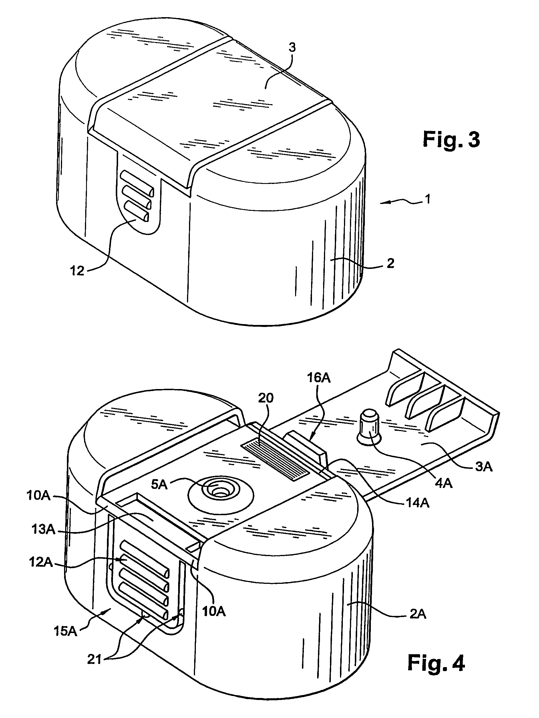
[0038]According to another feature of this second embodiment depicted in FIG. 4, the stopper 2A comprises means for releasing the shut-off flap which comprise a frontal pressing region 12A of an operating button 15A, secured to two lateral pivots 10A able to be articulated in two corresponding housings. Said pressing region 12A is extended at its upper part, beyond the articulation formed by the pivots 10a, towards the inside of the stopper 2A, by a lever 13A more or less perpendicular to the pressing region 12A and able to perform lifting by rotation against an internal part of the free end of the shut-off flap 3A away from the hinge 14A when pressure is exerted on the pressing region of the operating button 15A, until such time as the pip 4A is released from the pouring hole 5A.

[0039]As before, the shut-off flap 3A comprises internal reliefs 16A constituting pressing ridges produced on an internal region of said flap 3A at its free end away from the hinge 14A, facing that part of ...


PUM


Abstract

A closure device for a container, particularly a bottle, has a stopper called the service cap, arranged at the end thereof, on which a closing flap pivots. The closure device is provided with a locking system and cooperates with a hole in the sealed closure, or can be opened by pivoting. The closing flap has an opening device to guarantee the complete pivoting of the closing flap on opening, by a constant force and a constant movement without manual action of the user, immediately after the same has carried out a voluntary manual operation on the closing flap which is limited to releasing the locking system thereof.

Description

BACKGROUND OF THE INVENTION[0001](1) Field of the Invention[0002]The present invention relates to a device for opening-closing a container, particularly a bottle, consisting of a stopper known as the “service cap” arranged at its end and to which there is articulated a shut-off flap.[0003]This shut-off flap is equipped with an internal peg intended to collaborate in sealed closure with a pouring hole formed at the upper part of the stopper. This flap is intended to be made to open by flipping.[0004](2) Prior Art[0005]In this type of device, the shut-off flap is made to open by direct action on one of the ends, the opposite end to the hinge, accompanying it by hand, generally using the thumb of the same hand, over at least part of its opening travel or until it reaches a flip-over point.[0006]Whether this be in the first instance or in the second in the case of large stoppers, difficulties are encountered in accompanying the opening of the shut-off flap, particularly when one's hands...

Claims


Application Information

Patent Timeline
Patent Type & Authority Patents(United States)
IPC IPC(8): B65D39/00B65D47/08
CPCB65D47/0828B65D2251/1041B65D2251/1066
Inventor HENNEMANN, PASCALLAUTRE, PHILIPPERUSCONI, DOMINIQUE
Owner PLASTOHM SA
Why Eureka
Try Eureka