
Clamping apparatus of a puller

a technology of clamping apparatus and puller, which is applied in the direction of metal working apparatus, lifting device, metal-working apparatus, etc., can solve the problems of inconvenient installation of the puller for the bearing a, and achieve the effect of reducing displacement, easy installation, and increasing rang

Inactive Publication Date: 2010-02-02
HU CHIH KUO
View PDF8 Cites 31 Cited by
  • Summary
  • Abstract
  • Description
  • Claims
  • Application Information

AI Technical Summary

Benefits of technology

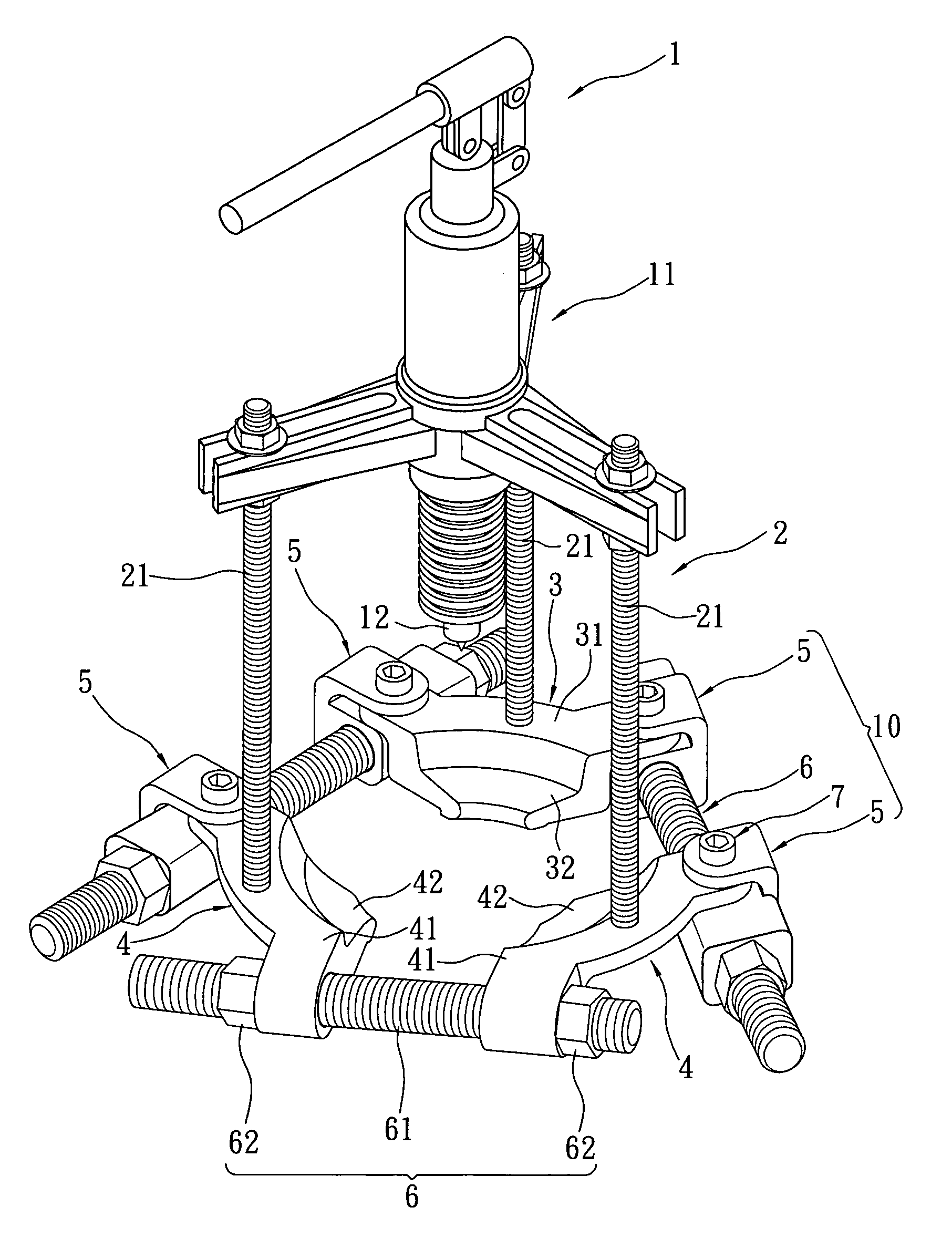
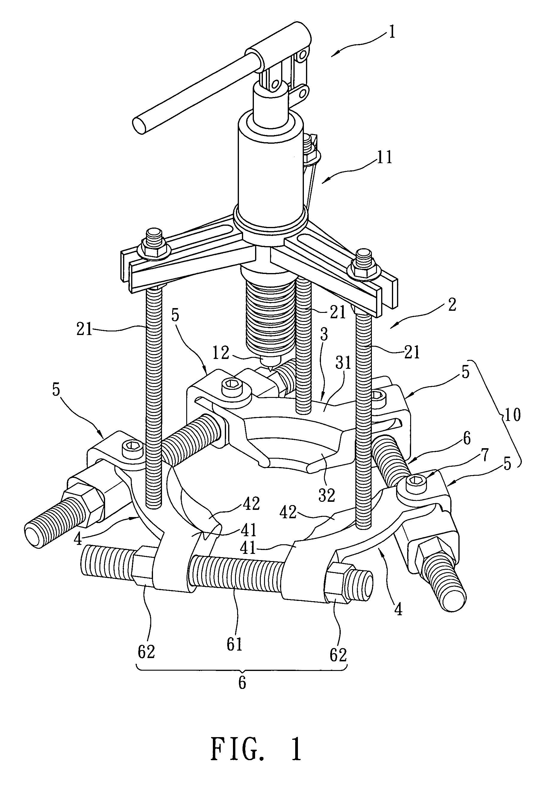
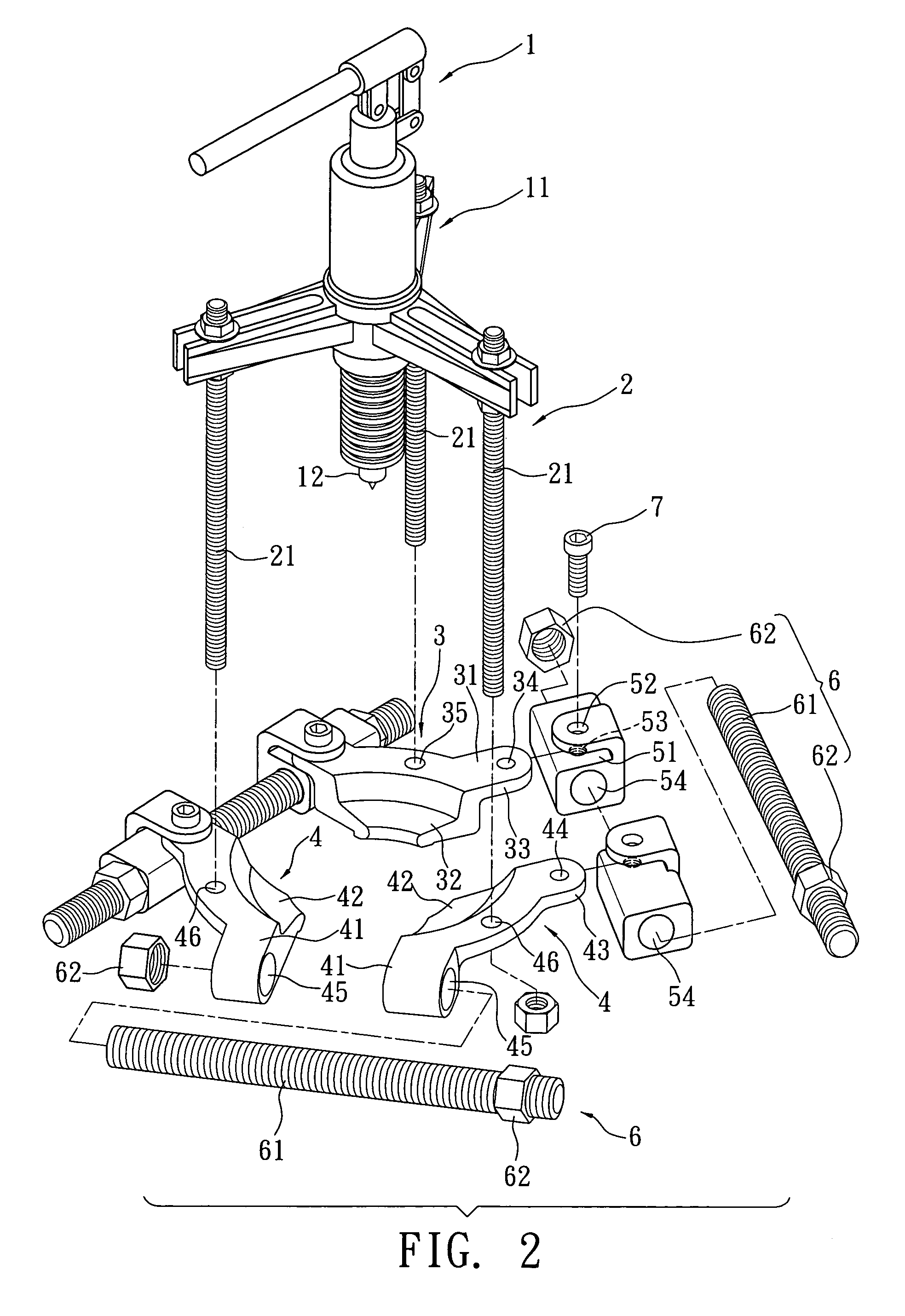
"The present invention provides a clamping apparatus for a puller that overcomes shortcomings of the prior art. The clamping apparatus includes a first clamping element, two second clamping elements, four pivoting elements, and three adjusting rod modules. The first clamping element has a main body and a clamping portion with a height difference, and the second clamping elements have a main body and a clamping portion with a height difference. The second clamping elements also have a pivotal connecting portion and a transverse penetrating hole. The pivoting elements are pivotally coupled to the first and second clamping elements, and the adjusting rod modules are connected and arranged substantially in a triangular shape. The technical effects of the invention include automatically guiding the clamping apparatus to an appropriate position, increasing the range between the clamping element for clamping the bearing, minimizing the displacement caused by the increased distance between the clamping elements, and simplifying the process of loosening the screw nuts to achieve the effect of installing the clamping apparatus easily."

Problems solved by technology

Obviously, the aforementioned puller used for the installation of the bearing A is very inconvenient.

Method used


Image

  • Clamping apparatus of a puller
  • Clamping apparatus of a puller
  • Clamping apparatus of a puller

Examples


Embodiment Construction

[0027]Referring to FIGS. 1 to 10 for the preferred embodiments of the present invention, the embodiments are provided for the purpose of illustrating the present invention only, but not intended to limit the scope of the invention.

[0028]The first preferred embodiment of the present invention provides a clamping apparatus of a puller 10 as shown in FIGS. 1 to 5, and the clamping apparatus is installed at the bottom of an actuating element 11 of a puller 1, and the actuating element 11 includes a driving element 12 abutting a bearing B and an adjusting element 2 having three pulling rods 21, wherein the clamping apparatus 10 comprises:

[0029]a first clamping element 3, substantially in an arc shape, and having a main body 31 and a clamping portion 32, and the clamping portion 32 and the main body 31 having a height difference, and the main body 31 having a pivotal connecting portion 33 disposed on both arc-shaped ends, wherein the pivotal connecting portion 33 of this embodiment has a ...


PUM

PropertyMeasurementUnit
heightaaaaaaaaaa
shapeaaaaaaaaaa
distanceaaaaaaaaaa

Abstract

A clamping apparatus of a puller includes a first clamping element, two second clamping elements, four pivoting elements and three adjusting rod modules. Each pivoting element is pivotally coupled to both ends of the first clamping element and an end of each second clamping element corresponding to the first clamping element. Another end of each second clamping element has a transverse penetrating hole. One of the adjusting rod modules is passed through a penetrating hole of each second clamping element, and the other two adjusting rod modules are passed through the penetrating hole of each pivoting element, so that the adjusting rod modules are arranged substantially in a triangular shape. The pivoting element is installed between the clamping elements for pivotally turning each adjusting rod module and automatically guiding to the central position and increasing the range between the clamping elements for mounting and installing a bearing easily.

Description

BACKGROUND OF THE INVENTION[0001]1. Field of the Invention[0002]The present invention relates to a clamping apparatus of a puller, and more particularly to a clamping apparatus capable of increasing the range between clamping elements of a puller by a pivoting element for mounting a bearing, and automatically guiding the bearing to a central position for a quick installation of the bearing.[0003]2. Description of the Related Art[0004]Referring to FIG. 11 for a traditional puller 9, the puller 9 includes a driving element 91, a contractable rod 92, three pulling rods 93, three clamping elements 94 and three adjusting rod modules 95. The driving element 91 is connected to the three pulling rods 93, and an end of each pulling rod 93 is connected to a clamping element 94, and each adjusting rod module 95 is passed into an end of one of the two clamping elements 94, and each clamping element 94 is integrated with the adjusting rod modules 95 to form a circular shape to facilitate install...

Claims


Application Information

Patent Timeline
Patent Type & Authority Patents(United States)
IPC IPC(8): B23P19/04
CPCB66F3/36Y10T29/53861Y10T29/5387Y10T29/53843
Inventor HU, CHIH KUO
Owner HU CHIH KUO
Learn More