

Charged particle beam equipment
a technology of chargeable particles and equipment, applied in the field of chargeable particle beam equipment, can solve the problems of time-consuming operation and complex adjustment of the rotation operation, and achieve the effect of improving operability and operation precision
- Summary
- Abstract
- Description
- Claims
- Application Information
AI Technical Summary
Benefits of technology
Problems solved by technology
Method used
Image

Examples
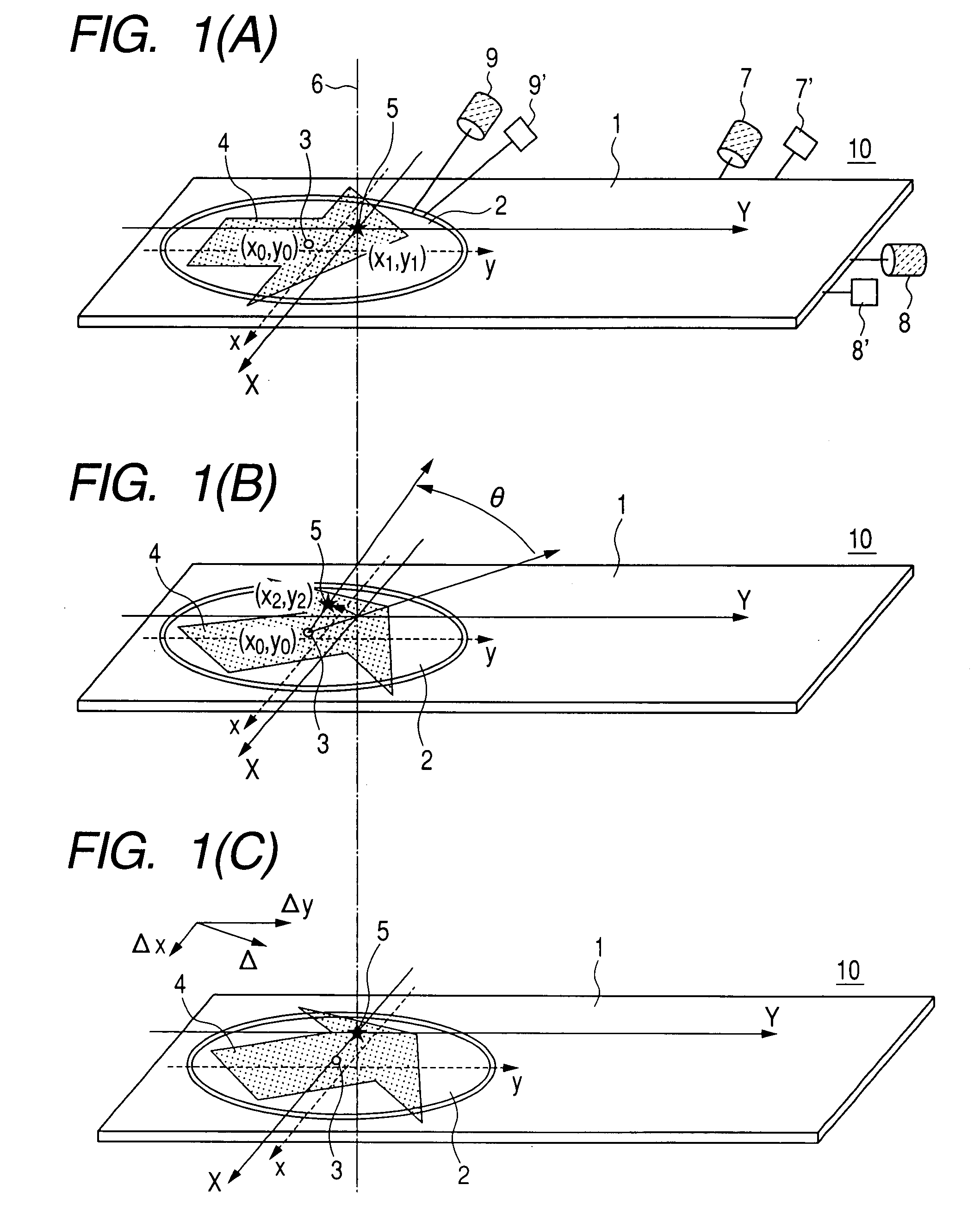
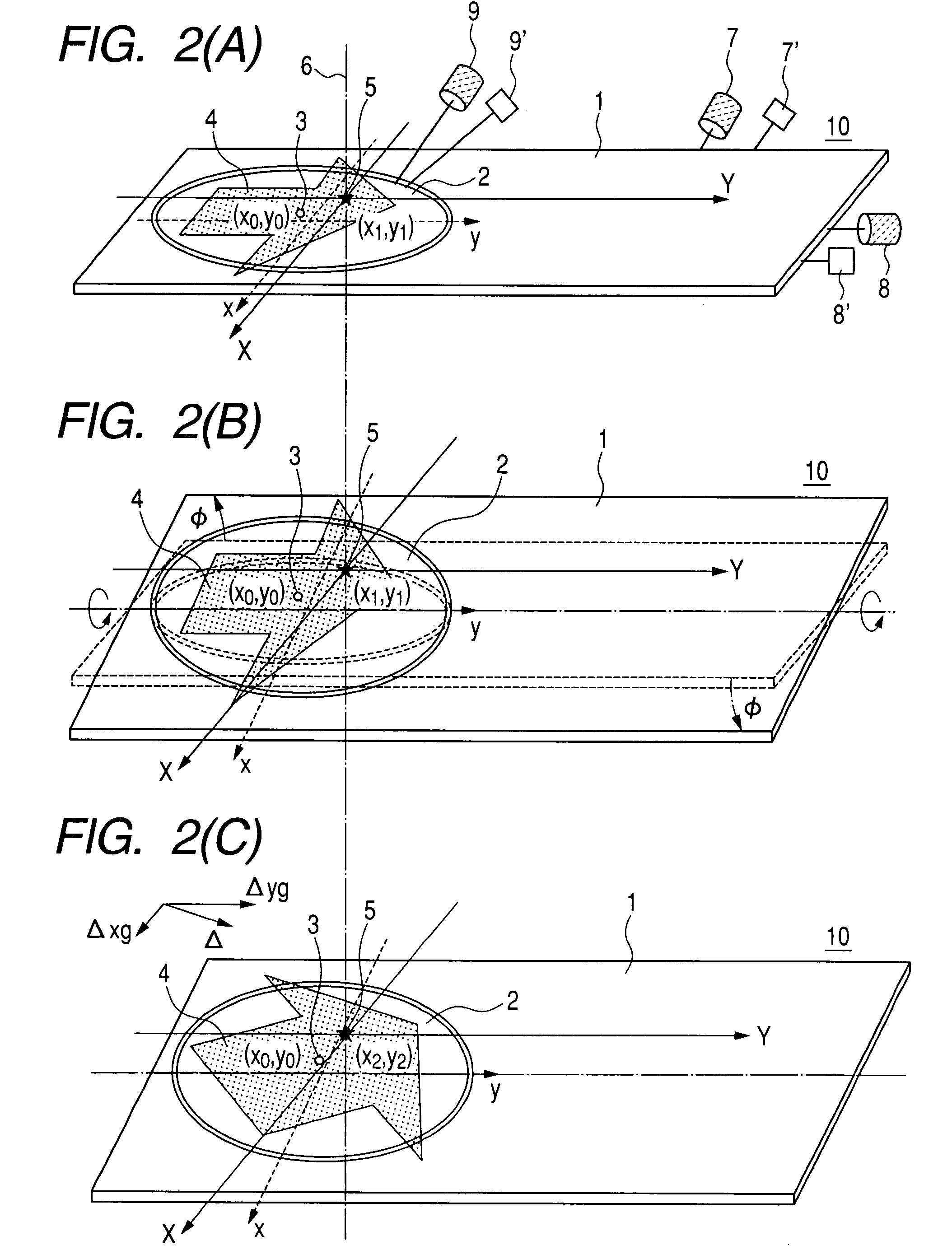
first embodiment
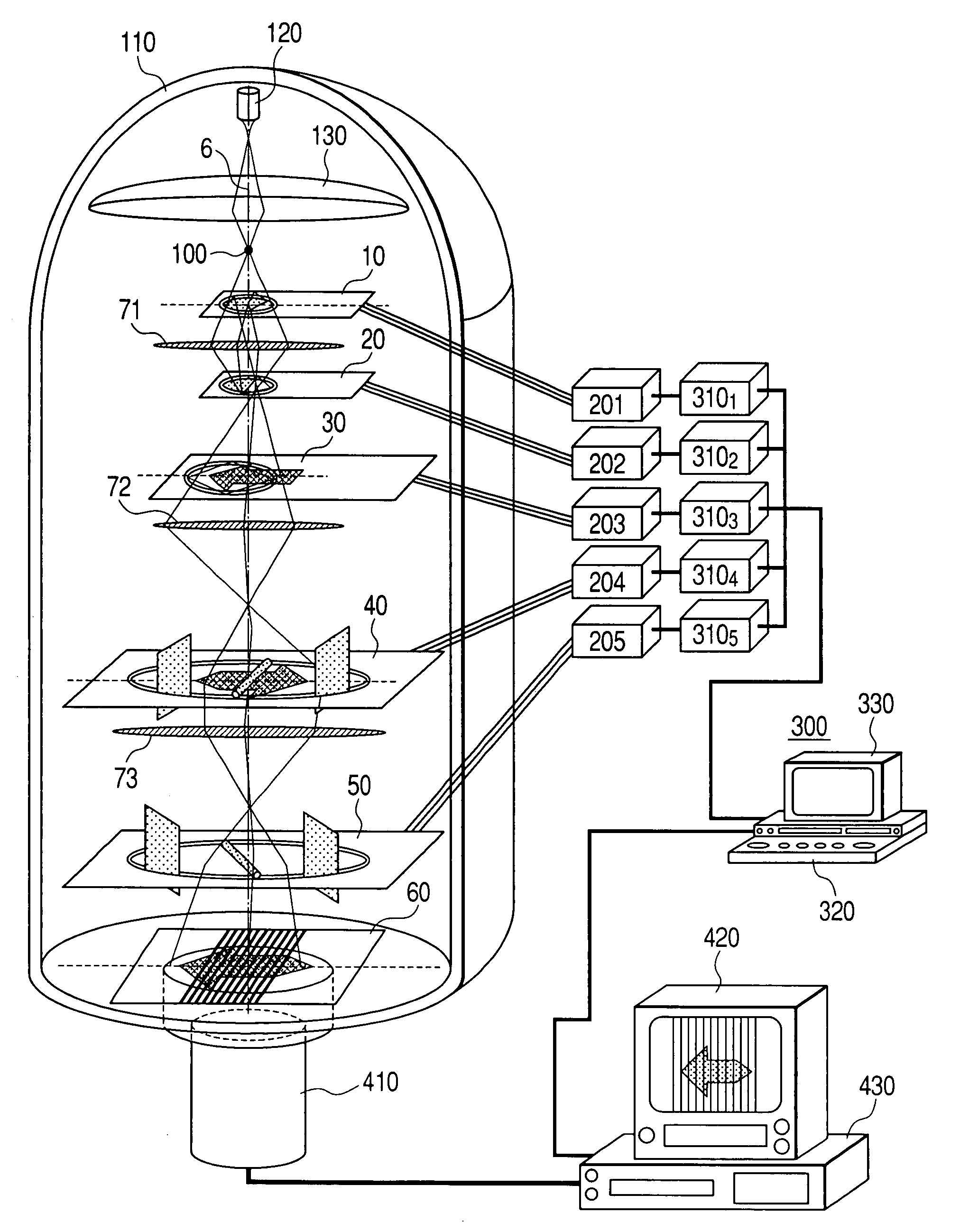
[0012]In the following, an explanation will be given, taking a sample holder as an example. However, explanation will be the same for equipment having other rotary mechanism.
[0013]FIGS. 1A to 1C are diagrams for explaining a rotation operation of a sample holder and a correction operation that becomes necessary incident to this. A reference numeral 10 is a sample holder. The sample holder 10 consists of a holder plate 1 and a rotatable sample hold 2 that is provided at an end thereof. A reference numeral 3 is a rotation center of the sample hold 2. A reference numeral 4 is a sample placed and held on the sample hold 2. A reference numeral 5 is an observing or machining point of the sample 4. Here, a coordinate system that is fixed to the charged particle beam equipment is expressed by the X-axis and Y-axis, whereas an optical axis of the optical system represented by an alternate long and short dash line is a Z-axis Moreover, a coordinate system that is fixed on this sample holder 1...
PUM
| Property | Measurement | Unit |
|---|---|---|
| rotation angle | aaaaa | aaaaa |
| angle | aaaaa | aaaaa |
| angle | aaaaa | aaaaa |
Abstract
Description
Claims
Application Information