
Recursive 3D model optimization

a three-dimensional model and optimization technology, applied in the field of three-dimensional modelling, can solve the problems of complex and expensive optical or mechanical equipment, inability to duplicate cheap consumer goods, physical cumbersome, etc., and achieve the effect of maximizing the correlation between the data generated and the model

Inactive Publication Date: 2010-02-02
NAT RES COUNCIL OF CANADA
View PDF8 Cites 29 Cited by
  • Summary
  • Abstract
  • Description
  • Claims
  • Application Information

AI Technical Summary

Problems solved by technology

However, one capability that still cannot be duplicated by these cheap consumer goods is the ability to create three dimensional (3D) models of objects.
One option for combining these views is the use of complex and expensive optical or mechanical equipment to track the scanning as one complete scan.
Clearly, the first option is complex, physically cumbersome, and potentially very expensive.
Another major drawback of the existing systems is their requirement that the object being scanned be fixed and stable during the scanning process.
Any undesired movement or vibration will introduce distortions and errors into the range data and thereby produce erroneous results.

Method used


Image

  • Recursive 3D model optimization
  • Recursive 3D model optimization
  • Recursive 3D model optimization

Examples


Embodiment Construction

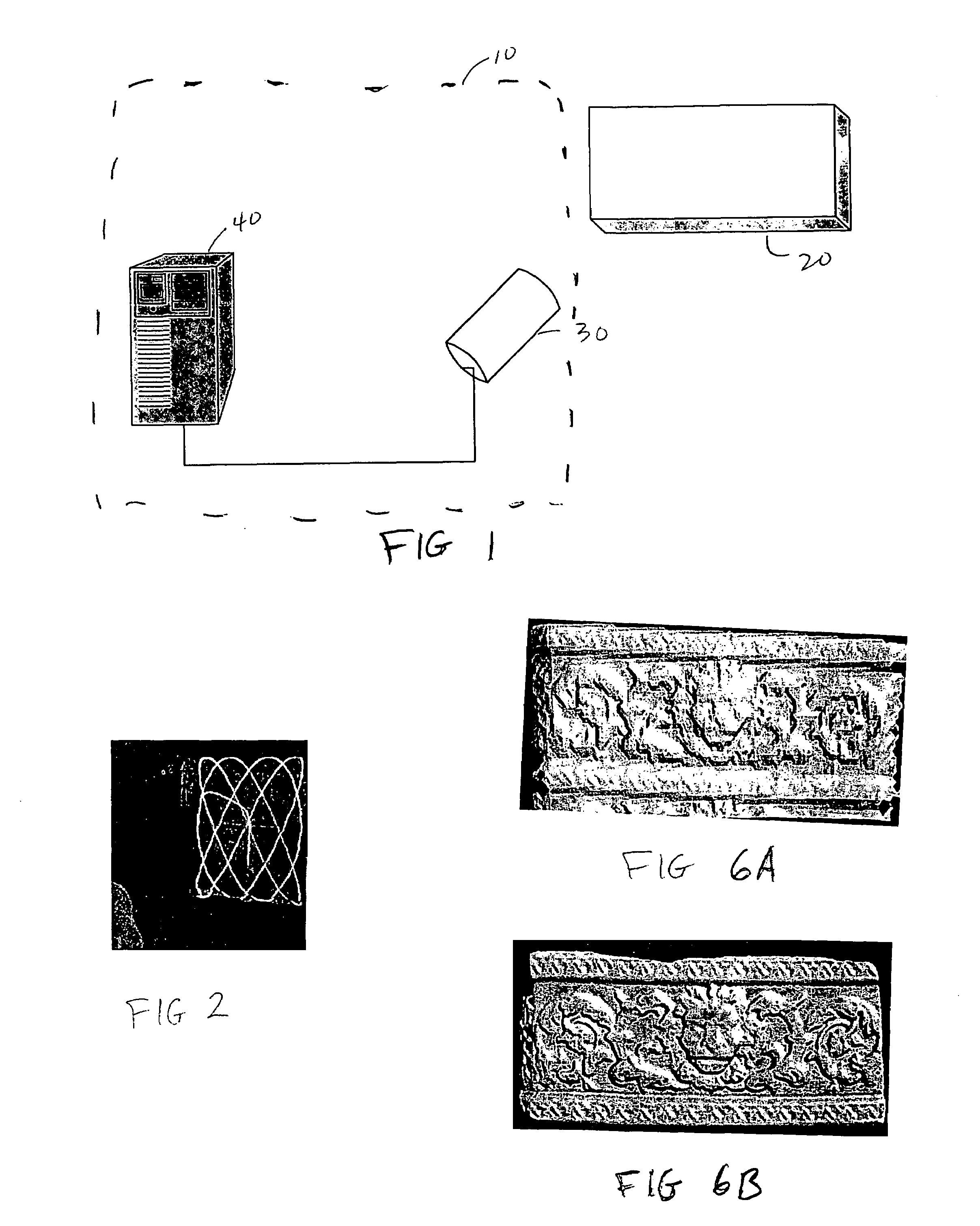
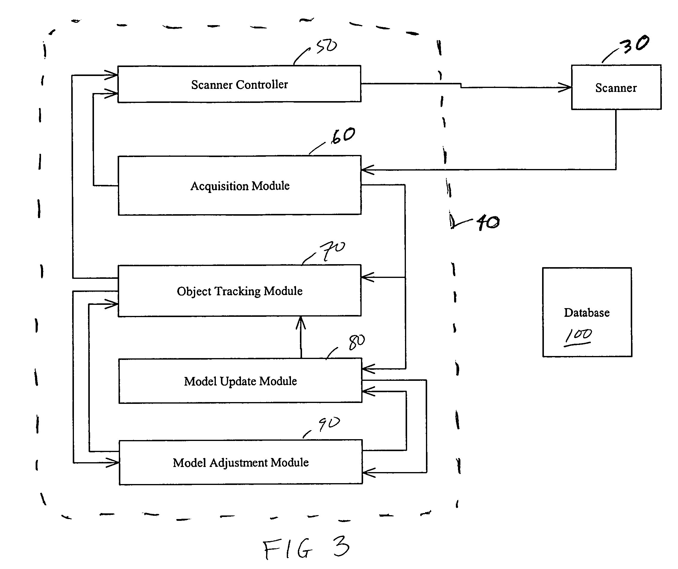
[0034]Referring to FIG. 1, a system 10 for generating and optimizing a 3D model of an object 20 is illustrated. The system 10 consists of a scanner 30 and a data processing subsystem 40. The data processing subsystem 40—controls the scanning of the object 20 by the scanner 30 and receives scan data from the scanner 30. The data processing subsystem 40 also processes the scan data from the scanner 30 to create a 3D model of the object 20.

[0035]One of the methods which may be used by the data processing subsystem 40 in processing the scan data is what is known as ICP (Iterative Closest Point) methods. Mathematically, the objective of these ICP methods is to find the rigid transformation matrix Mk that will align the range data set Xk in the scanner coordinate system with the model reference image data set xmk where

xmk=Mkxk

xk=[x y z1]T

[0036]To use these methods, it is assumed that the images are rigid, accurate, and stable during the acquisition. As noted above, the prior art uses co...


PUM


Abstract

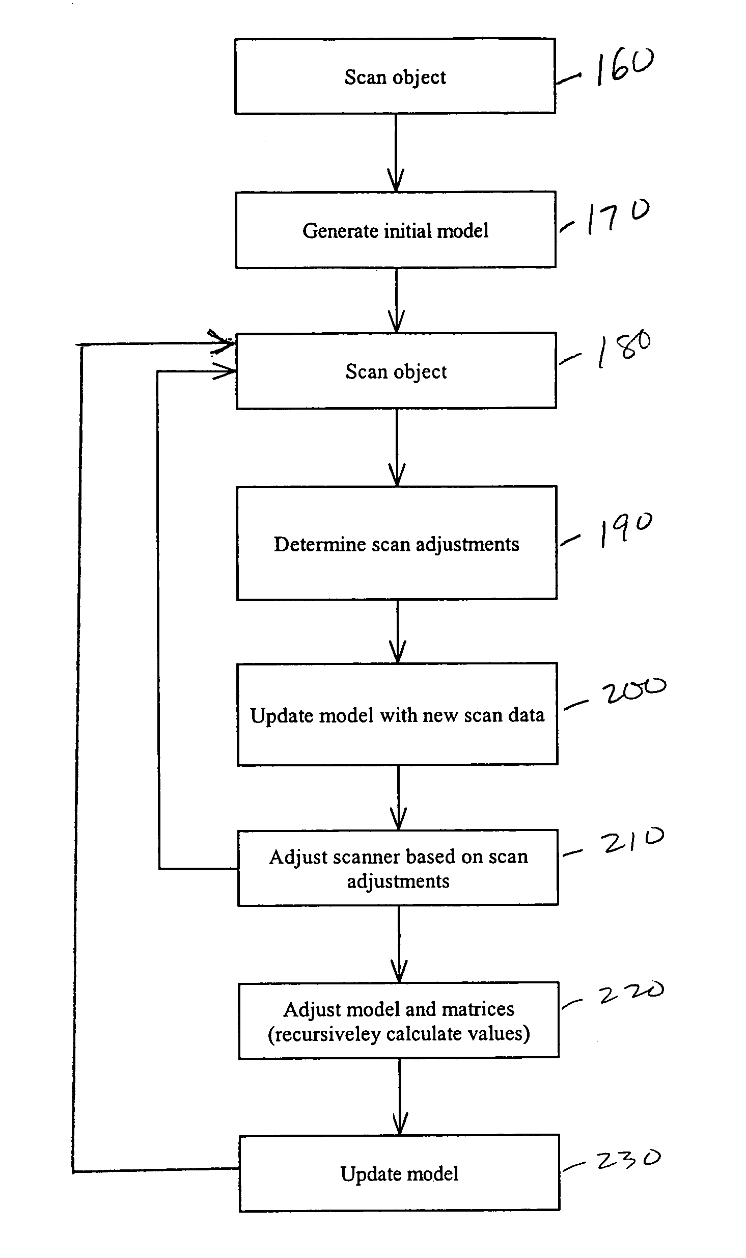
Systems and methods for generating and optimizing 3D models of objects. A laser scanner is controlled by a data processing subsystem that controls the scanning and processes the data generated. From an initial model, either a raster scan of the object or an initial scan, the system scans the object multiple times, each time adjusting the laser scanner to maximize a correlation between the data generated and the model. The model is also updated using the scan data and taking into account the adjustments which were applied to the laser scanner. Other adjustments, such as those which would remove the effect of relative motion on the scan data, are also accounted for when incorporating scan data into the model. The model is recursively adjusted and optimized using previous scan data (both pre-recorded and fresh scan data) and previous adjustments. The model may be modified and adjusted using previous scan data and an Iterative Closest Point method. The method and systems may be used in uncontrolled environments where unpredictable motions and vibrations can occur. The invention may be used with scanners mounted on a robotic arm, scaffolding, unstable tripods, at the tips of booms or lifts, or the scanners may be simply held by hand.

Description

FIELD OF THE INVENTION[0001]The present invention relates to three dimensional modelling and, more specifically, it relates to systems and methods for generating and optimizing three dimensional models of objects.BACKGROUND TO THE INVENTION[0002]The recent growth in interest in digital photography and digital imaging has been fuelled by the dropping costs of digital cameras and flatbed scanners. However, one capability that still cannot be duplicated by these cheap consumer goods is the ability to create three dimensional (3D) models of objects.[0003]As is currently known, 3D scanners can only measure one view of an object at a time. To completely reconstruct an object, multiple images must be acquired from different orientations. One option for combining these views is the use of complex and expensive optical or mechanical equipment to track the scanning as one complete scan. Another option would be to perform separate scans and use software to digitally combine the images together...

Claims


Application Information

Patent Timeline
Patent Type & Authority Patents(United States)
IPC IPC(8): G06K9/00
CPCG01S17/89G06T7/0026G06T2200/08G06T7/32
Inventor BLAIS, FRANCOISPICARD, MICHEL
Owner NAT RES COUNCIL OF CANADA
Learn More