Backlight device and display device comprising backlight device

a backlight device and display device technology, applied in the direction of instruments, lighting and heating apparatus, optical elements, etc., can solve the problems of color unevenness and brightness unevenness on the image display surface, and achieve the effects of reducing brightness unevenness and color unevenness, preventing the crease of the reflection sheet, and correctly maintaining the positional relationship

Inactive Publication Date: 2010-02-09
SHARP KK
View PDF9 Cites 47 Cited by
  • Summary
  • Abstract
  • Description
  • Claims
  • Application Information

AI Technical Summary

Benefits of technology

[0008]The present invention has been made with the aim of solving the above problems, and it is a main object of the invention to provide a backlight device and a display device, capable of reducing brightness unevenness and color unevenness on the image display surface resulting from the light emitting diode substrate by placing a reflection sheet on the front side of the light emitting diode substrate and providing the reflection sheet with a through-hole into which the light emitting diode is inserted.
[0034]According to the present invention, it is possible to make the number of the light emitting diodes in the long-side direction of the panel module less than the number of the light emitting diodes in the short-side direction and reduce the weight, and it is also possible to prevent the circumferential surface of the through-hole of the reflection sheet from coming into contact with the circumferential surface of the light emitting diode due to thermal expansion of the reflection sheet.

Problems solved by technology

In the device of Japanese Patent Application Laid-Open No. 2004-139876, however, the figure of the light emitting diode substrate and the color of the light emitting diode substrate appear on the image display surface of the panel module, and cause brightness unevenness and color unevenness on the image display surface.

Method used


Image

  • Backlight device and display device comprising backlight device
  • Backlight device and display device comprising backlight device
  • Backlight device and display device comprising backlight device

Examples


embodiment 1

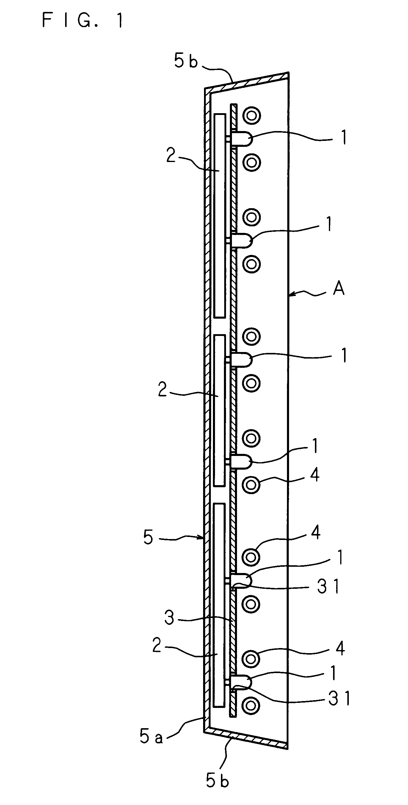
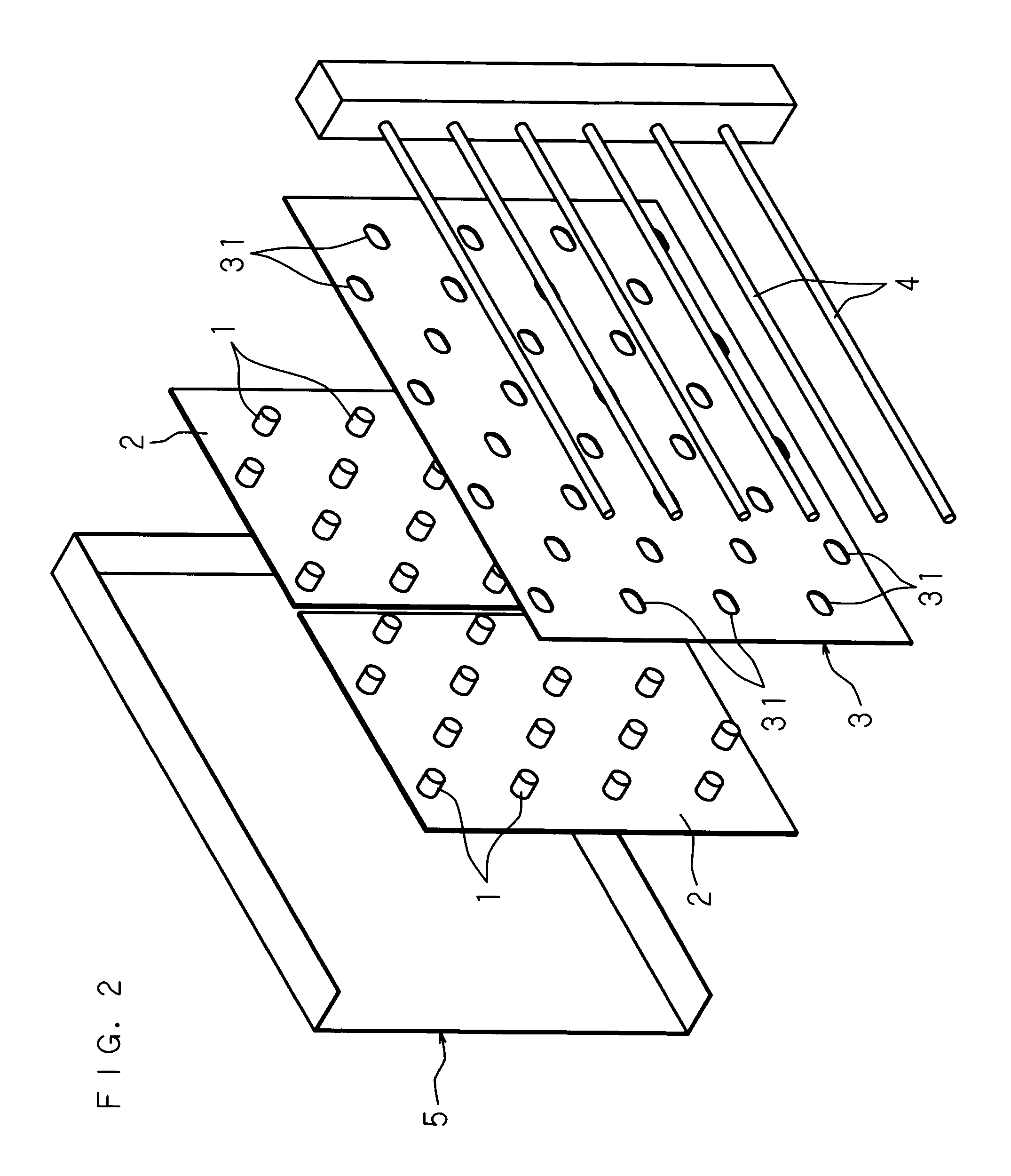
[0045]FIG. 1 is a schematic cross sectional view showing the structure of Embodiment 1 of a backlight device according to the present invention, FIG. 2 is an exploded perspective view of the backlight device, and FIG. 3 is an explanatory view showing the relationship between light emitting diodes and through-holes of a reflection sheet.

[0046]A backlight device A illustrated in the drawings comprises a plurality of light emitting diode substrates 2 having three or more light emitting diodes 1 arranged with a distance therebetween in two orthogonal directions; a reflection sheet 3 placed on the light emitting diode 1 side of the light emitting diode substrates 2 and having through-holes 31 into which the light emitting diodes 1 are inserted; a plurality of cylindrical fluorescent tubes 4 aligned; and a housing 5 for storing and supporting the light emitting diode substrates 2, reflection sheet 3 and fluorescent tubes 4.

[0047]The housing 5 has a base wall 5a, and four side walls 5b joi...

embodiment 2

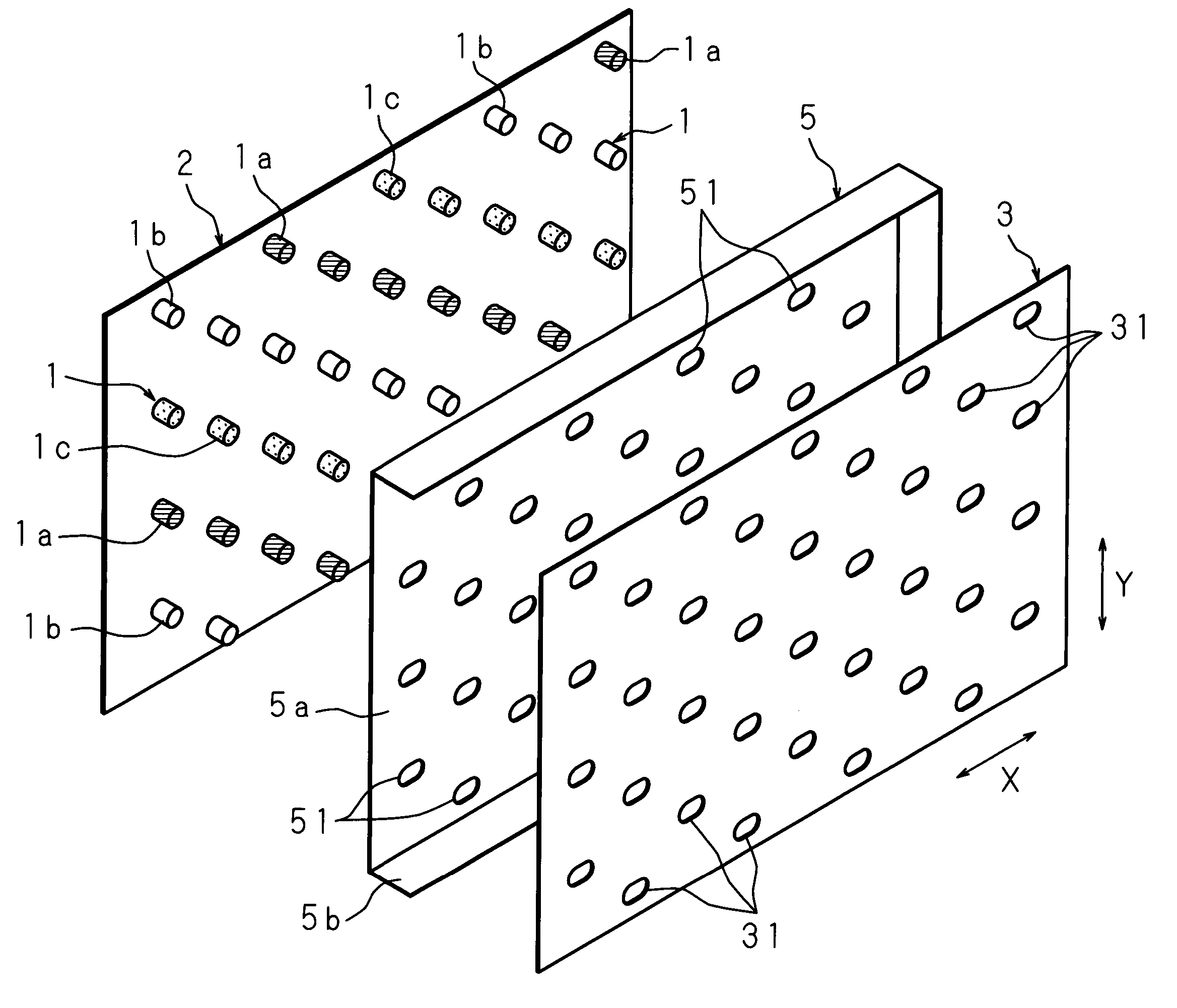
[0060]FIG. 5 is a schematic cross sectional view showing the structure of Embodiment 2 of a backlight device according to the present invention, FIG. 6 is an exploded perspective view of the backlight device, and FIG. 7 is a schematic cross sectional view showing another structure of a display device according to the present invention. In this backlight device, instead of arranging a plurality of light emitting diode substrates 2 in the housing 5, the light emitting diode substrate 2 are arranged outside the base wall 5a of the housing 5; insertion holes 51 corresponding to the light emitting diodes 1 of the light emitting diode substrates 2 are formed in the base wall 5a of the housing 5; and the reflection sheet 3 of Embodiment 1 is supported on the inner side of the base wall 5a of the housing 5 formed using a metal material.

[0061]The light emitting diodes 1 of each light emitting diode substrate 2 include first elements 1a for emitting red light, second elements 1b for emitting ...

embodiment 3

[0065]FIG. 8 is a schematic cross sectional view showing another structure of the backlight device according to the present invention, and the structure of a display device comprising this backlight device. In this backlight device, an inverter circuit substrate 8 is provided outside the light emitting diode substrates 2 of Embodiment 2, and the inverter circuit substrate 8 is supported on the base wall 5a of the housing 5.

[0066]Since other structures and functions are the same as in Embodiments 1 and 2, similar parts are designated with the same codes, and the detailed explanation and the explanation of the functions and effects are omitted.

[0067]Although the embodiments described above illustrate the structures including the fluorescent tubes 4, it may be possible to construct the present invention without the fluorescent tubes 4.

[0068]Moreover, in the embodiments described above, the through-holes are elliptical in shape, but the through-holes may be rectangular or substantially ...


PUM


Abstract

In a backlight device according to the present invention including a light emitting diode substrate, which has a light emitting diode and is placed on the back side of a panel module having an image display surface on the front side, and a reflection sheet for reflecting light emitted by the light emitting diode to the panel module, the reflection sheet is placed on the front side of the light emitting diode substrate, and the reflection sheet is provided with a through-hole into which the light emitting diode is inserted, so as to reduce brightness unevenness and color unevenness on the image display surface resulting from the light emitting diode substrate.

Description

CROSS-REFERENCE TO RELATED APPLICATIONS[0001]This non-provisional application claims priority under 35 U.S.C. §119(a) on Patent Application No. 2005-271067 filed in Japan on Sep. 16, 2005, the entire contents of which are hereby incorporated by reference.BACKGROUND OF THE INVENTION[0002]1. Field of the Invention[0003]The present invention relates to a backlight device for use as a light source of a liquid crystal display device, and a display device comprising the backlight device.[0004]2. Description of Related Art[0005]In a display device such as a television, a backlight device is placed on the back side of a panel module having an image display surface for displaying an image on the front side thereof.[0006]As a backlight device, for example, there is a known backlight device comprising a light emitting diode substrate having light emitting diodes, and a reflection sheet for reflecting light emitted by the light emitting diodes to the panel module, wherein the light emitting dio...

Claims


Application Information

Patent Timeline
Patent Type & Authority Patents(United States)
IPC IPC(8): G09F13/04G09F13/08
CPCG02F1/133603G02B6/0068G02F1/133604G02F1/133605
Inventor MORIYASU, MITSUHIRONAMIKI, TORU
Owner SHARP KK
Why Eureka
Try Eureka