Golf club grip

a golf club and grip technology, applied in the field of golf club grips, can solve the problems of poor golf shots, dominance of the golf swing control of the lower hand, increase the difficulty of repeating the golf swing, and increase the difficulty of golfing the golf club holding the golf club, so as to improve the feel and control of the golf club

Active Publication Date: 2010-02-09
FERRIS RICHARD D
View PDF12 Cites 3 Cited by
  • Summary
  • Abstract
  • Description
  • Claims
  • Application Information

AI Technical Summary

Benefits of technology

[0010]The present invention relates to a full swing golf club grip having three separately sized sections to enhance feel and control of the golf club during the execution of a golf shot. The grip structure includes an upper section closest to the upper end of the golf club having a first constant diameter sized to be engaged by the last two fingers of the weaker, upper hand. The grip structure includes a second tapered transitional section that is tapered with a gradually increasing outer diameter as it extends away from the upper section toward the lower section of the golf grip. This tapered transitional section creates a grasping area for the middle finger, index finger and thumb of the weaker, upper hand. The lower section interfaces with the end of the tapered transitional section and has a constant diameter greater than the diameter of the upper section.
[0011]All sections of the grip are manufactured in a manner forming a unitary golf club grip for both hands of the golfer holding the golf club. This grip configuration provides a separate feel to each hand as the club is gripped. The grip configuration, combined with the natural anatomy of the golfer's hand, allows the golf club to be held firmly without creating a shaft angle (that is, an angle between the golfer's leading arm and the shaft) at set-up (address). This is accomplished by the fingers of the upper hand each moving equal distances despite the overall difference in the anatomy of the fingers as the club is grasped tightly. This eliminates the fulcrum action of the fingers on the club grip relative to each other. That is, the design of the grip prevents the club head from rising off the ground as the grip is squeezed and creates an angle between the golfer's arms and club shaft. This occurs due to the configuration of the grip with a smaller diameter upper section, a tapered transitional section and a larger diameter lower section.
[0012]During the golf swing, the following benefits accrue to the golfer using the present grip. An erect set-up posture with less of a spine angle is more easily created. The golfer is better able to employ a one-plane swing; spine angle changes during the execution of the full swing are reduced or eliminated; and the tendency to rotate the body up and out of the swing is greatly reduced.

Problems solved by technology

It is well known that control of the golf swing by the lower, or dominant, hand produces poor golf shots whereas consistent, powerful and accurate golf shots are produced when the non-dominant hand and arm control the golf swing.
Therefore, the positioning of the weaker, upper hand on the largest part of the golf club grip contributes to the difficulty of a golfer maintaining a solid hold on the golf club while executing a golf shot.
These additional swing movements increase the difficulty of executing a repeating golf swing thus requiring endless practice and repetition of the golf swing to produce a consistent, repeatable golf swing.
Conversely, because of the smaller size along the lower portion of the golf grip, it is difficult for the stronger hand to impart sufficient force to the club head to impart maximum flight and trajectory to the golf ball during the execution of a golf shot.
The smaller portion of the golf grip tends to cause premature release of the trailing, stronger hand resulting in a wide variety of errant golf shots.

Method used


Image

  • Golf club grip
  • Golf club grip
  • Golf club grip

Examples


Embodiment Construction

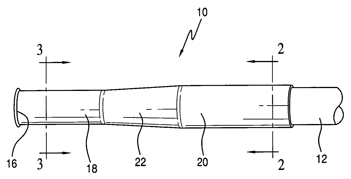
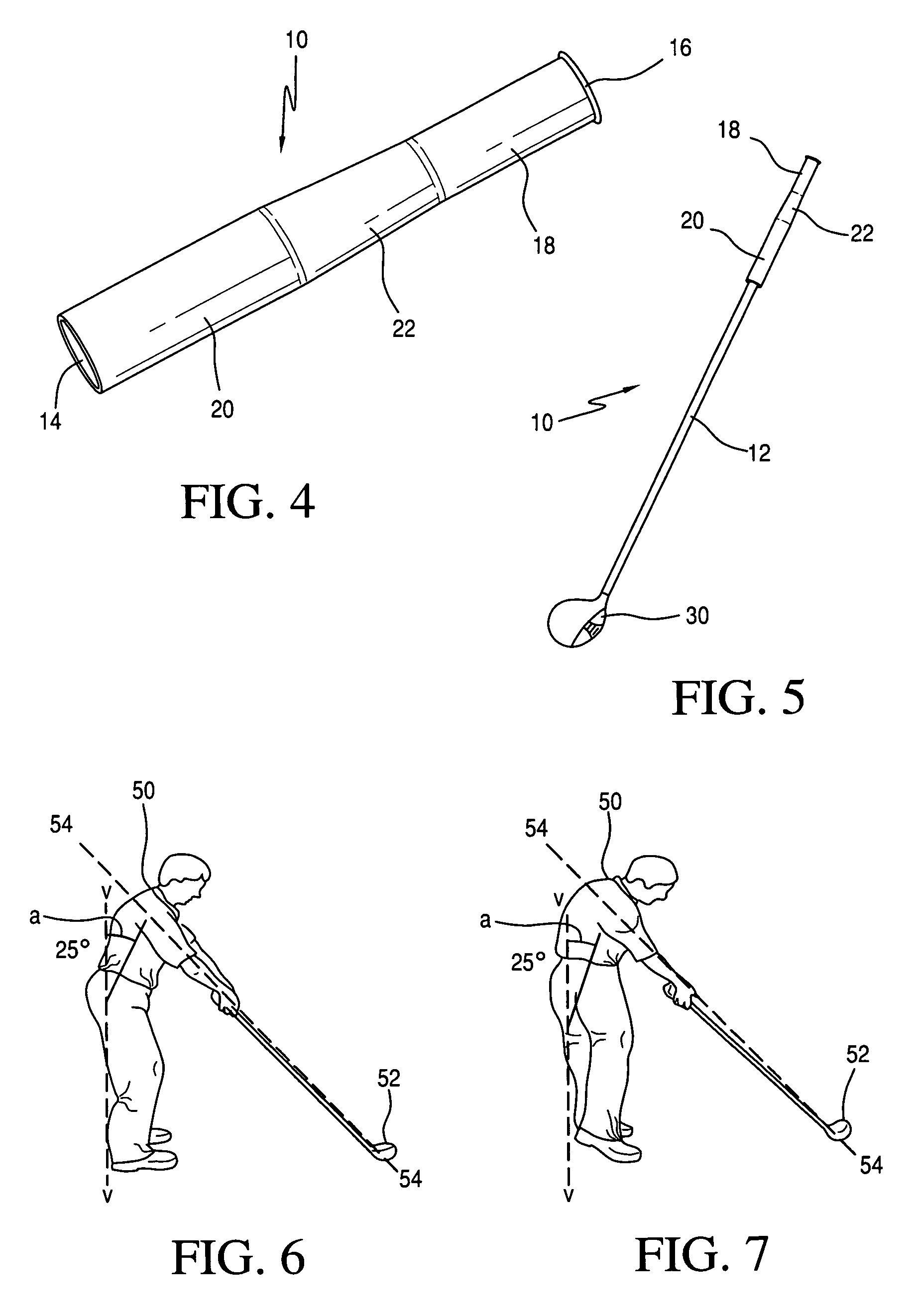
[0029]Referring to the drawings, a full swing golf club grip 10 in accordance with the present invention is shown positioned on a club shaft 12 with a club head 30 on the opposite end thereof. The grip 10 preferably is a molded, single, unitary unit and includes an opening 14 at the lower end of the grip 10 for insertion of a shaft 12 during assembly. A cap 16 is provided on the upper end of the grip 10 to cover the upper edges of the shaft 12. The grip 10 is formed of an upper section 18 having a first diameter, a tapered transitional area 22 having a gradually increasing diameter in a direction away from the upper section 18 and a lower section 20 formed with a second diameter greater than the diameter of the upper section 18. The tapered transitional section 22 connects the upper section 18 and lower section 20 whereby the entire grip 10 is formed of a single unitary piece of molded material. Both the upper section 18 and the lower section 20 have a constant, non-tapered, outer d...


PUM


Abstract

A golf club grip for attachment to a golf club shaft formed of an upper section having a first outer diameter, an intermediate tapered transitional area and a lower section having a second outer diameter larger than the upper section outer diameter. The upper section accommodates the ring finger and pinky finger of the upper hand. The intermediate tapered transitional section accommodates the middle and index fingers and the thumb of the upper hand. The lower section accommodates the fingers of the lower hand. The structure of the golf club grip promotes better feel and allows a golfer's non-dominant upper hand to obtain a firmer and stronger grip while allowing the dominant lower hand to impart more force to the ball with the golf club.

Description

CROSS REFERENCE TO RELATED APPLICATION[0001]This application is a continuation-in-part of International Application No. PCT / US06 / 45694, filed Nov. 30, 2006, entitled “Golf Club Grip”, which is currently pending; and this application is also a continuation-in-part of U.S. patent application Ser. No. 11 / 289,564, filed Nov. 30, 2005, entitled “Golf Club Grip”, which is now abandoned.BACKGROUND OF THE INVENTION[0002]The present invention relates to golf club grips and, in particular, to a golf club grip with an improved configuration.[0003]The game of golf is played using a golf ball and a variety of different golf clubs to strike the ball from a teeing area into a hole some distance away. Whereas the club heads vary widely, most golf clubs include a shaft attached to the club head and a grip or handle attached to the upper part of the shaft to enable a golfer to hold and swing the club.[0004]Typically a golfer grips the golf club with both hands, normally in close proximity to each oth...

Claims


Application Information

Patent Timeline
Patent Type & Authority Patents(United States)
IPC IPC(8): A63B53/14
CPCA63B53/14A63B49/08A63B69/36A63B60/14A63B60/10A63B60/08A63B60/12
Inventor FERRIS, RICHARD D.
Owner FERRIS RICHARD D
Why Eureka
Try Eureka