
Discrete optical correlation system with adjustable aperture

a technology of optical correlation and aperture adjustment, which is applied in the direction of instruments, lighting and heating apparatus, sensing by electromagnetic radiation, etc., can solve the problem of not enabling the convenient adjustment of a dispersed lighting system

Active Publication Date: 2010-02-16
KENNEDY DOUGLAS BRIAN +1
View PDF9 Cites 5 Cited by
  • Summary
  • Abstract
  • Description
  • Claims
  • Application Information

AI Technical Summary

Benefits of technology

"The present invention is about a system that produces discrete correlated or focused illumination output. The system includes a portable electrical illumination system and an optically opaque hollow module that can be coupled to the illumination system. The hollow module has at least two openings, a hollow internal region, an optically opaque outer surface, and a coupling mechanism. The invention also includes a portable chemical illumination system and an optically opaque hollow module that can be coupled to produce a discrete correlated or focused illumination output. Additionally, the invention includes an optically transparent illumination system and an optically opaque sleeve that can be coupled to produce a directed illumination output. The invention allows for the creation of an adjustable aperture between two optically opaque sleeves. The technical effects of the invention include the ability to produce discrete correlated or focused illumination output and the versatility of combining different portable illumination systems with the hollow module."

Problems solved by technology

Unfortunately, these systems do not enable a dispersed lighting system to be conveniently adjusted to provide discrete focused illumination.

Method used


Image

  • Discrete optical correlation system with adjustable aperture
  • Discrete optical correlation system with adjustable aperture
  • Discrete optical correlation system with adjustable aperture

Examples


second embodiment

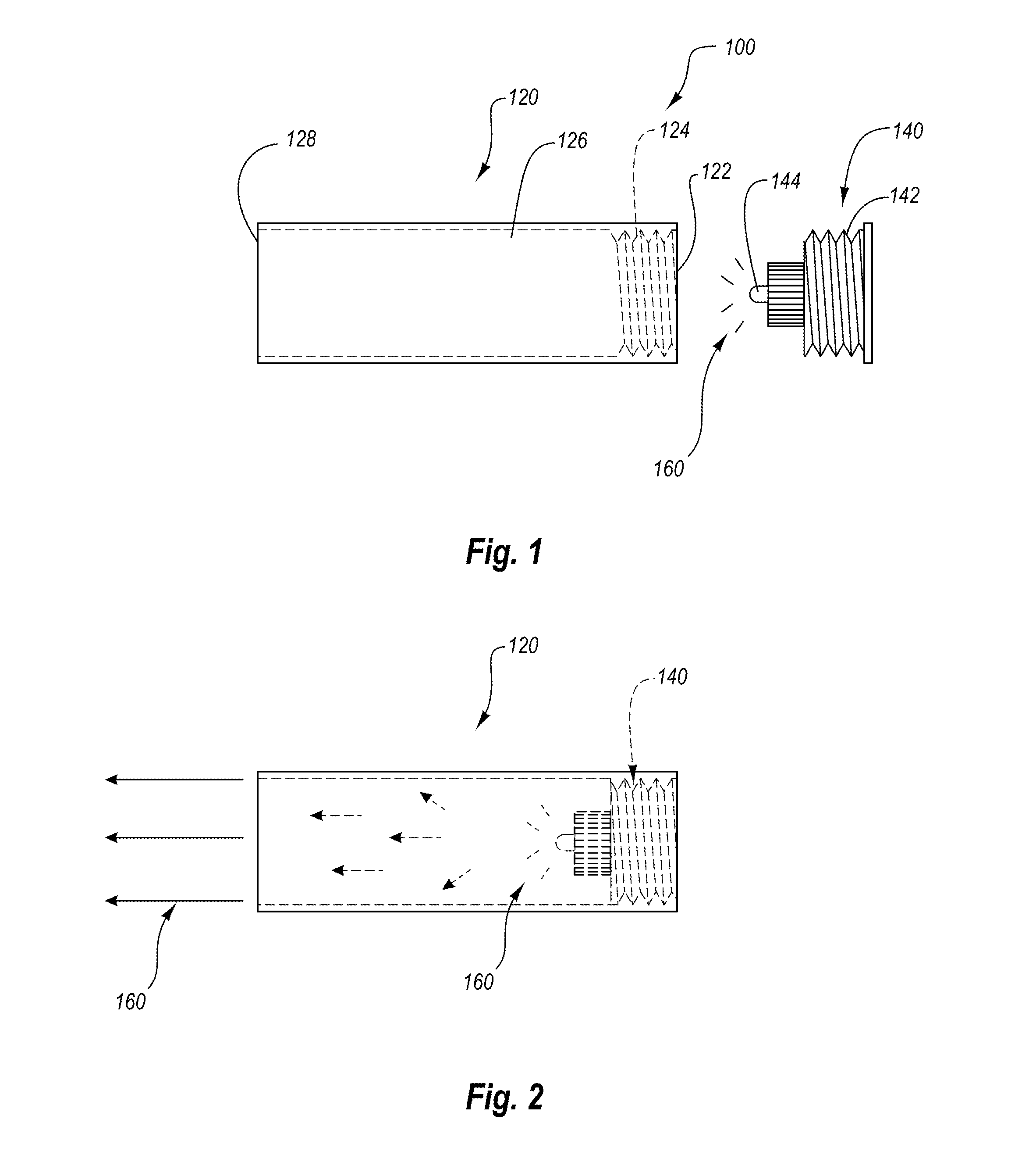
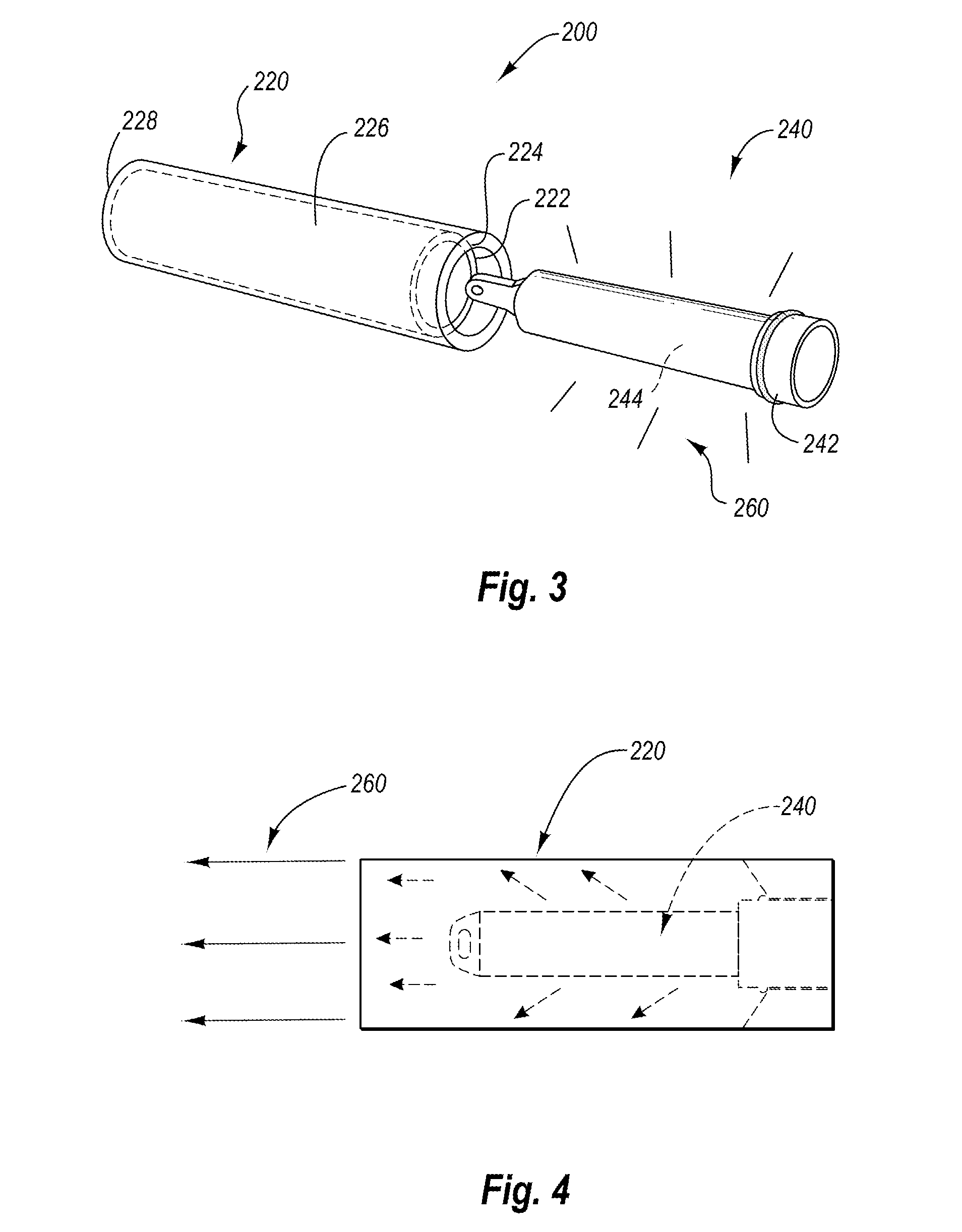
[0035]Reference is next made to FIG. 3, which illustrates a profile view of a discrete optical correlation system in accordance with the present invention, wherein the system is illustrated in a disassembled configuration. The system is designated generally at 200. The system 200 includes an optically opaque hollow module 220 and a chemical illumination system 240. The illustrated chemical illumination system 240 is a conventional glow stick or CYALUME™ that utilizes a contained chemical composition to generate illumination in response to a particular trigger. The illumination system 240 includes a contained chemical composition 244 surrounded by a translucent cover and cap 242. The contained chemical composition 244 transmits light 260 through the translucent cover and cap 242 in a dispersed and / or diffused optical pattern. Various other chemical illumination systems may also be utilized in the system 200 in accordance with the present invention including but not limited to KRILL™ ...

third embodiment

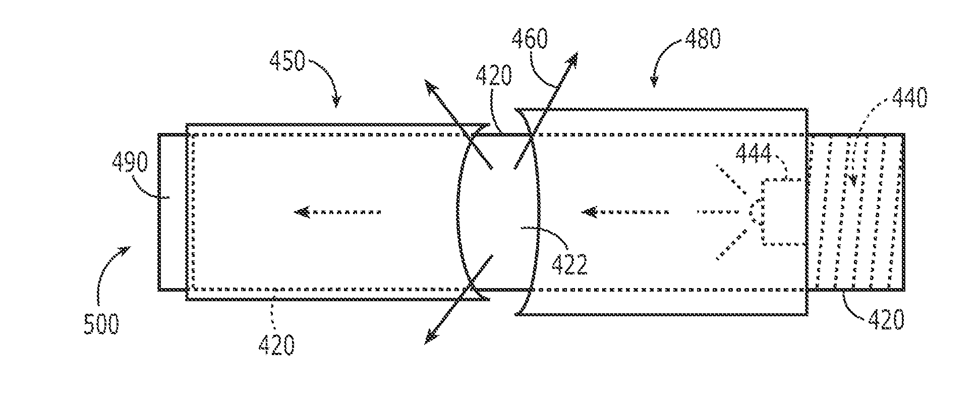
[0039]Reference is next made to FIG. 5, which illustrates a profile view of a discrete optical correlation system in accordance with the present invention, wherein the system is illustrated in a disassembled configuration. The system includes an elongated transparent optical illumination system 300 and an optically opaque sleeve 350. The optical illumination system includes an elongated transparent member 320 and a portable illumination system 340. The elongated transparent member 320 is shaped in the form of a hollow cylinder with two open sides. The elongated transparent member 320 is composed of a transparent or translucent material such as plastic. The illustrated portable illumination system 320 is an electrically based system, but it will be appreciated that other types of portable illumination systems may also be used in accordance with the present invention. The portable illumination system 340 includes an illumination source 344 that produces illumination 360. The portable ...

fourth embodiment

[0048]Reference is next made to FIGS. 10A-D and 11A-D which illustrate an alternative sleeve configuration in which the concave curved cutouts are disposed on widthwise straight ends rather than lengthwise circular ends as illustrated in previous embodiments. The alternative embodiment includes a first and second optically opaque sleeve 550, 580 with corresponding concave cutouts 552, 582 disposed on the widthwise straight ends of the first and second optically opaque sleeve 550, 580. The first and second optically opaque sleeves 550, 580 do not entirely form a tube but rather includes a gapped region between the first and second widthwise straight ends. In this alternative embodiment, the two sleeves 550 and 580 are disposed such that the two concave curved cutouts 552, 582 rotationally overlap one another to create a rotationally adjustable exposed transparent region over a corresponding transparent member (Such as element 420 in FIG. 8). As the first and second optically opaque s...


PUM


Abstract

The present invention relates to a discrete optical correlation system. One embodiment of the present invention includes a portable electrical illumination system and an optically opaque hollow module, configured to releasably couple to the portable electrical illumination system in a manner such that when the portable electrical illumination system is activated, the system produces a discrete correlated or focused illumination output. The portable electrical illumination system further includes a light emitting diode, a power source, a switch, and a coupling mechanism. The optically opaque hollow module further includes at least two openings, a hollow internal region, an optically opaque outer surface, and a coupling mechanism disposed on at least one of the at least two openings. A fourth embodiment relates creating an adjustable aperture between two optically opaque sleeves sliding over an optically transparent module coupled to the portable electrical illumination system.

Description

RELATED APPLICATIONS[0001]This is a continuation in part application claiming priority to U.S. utility application Ser. No. 11 / 462,794 filed Aug. 7, 2006 now U.S. Pat. No. 7,311,261, the contents of which are incorporated by reference.FIELD OF THE INVENTION[0002]The invention generally relates to portable optical illumination systems and accessories. In particular, the present invention relates to a discrete optical correlation system.BACKGROUND OF THE INVENTION[0003]Portable illumination systems may be used to provide illumination in both dispersed and focused light patterns. Dispersed illumination systems allow light to transmit in a variety of directions, while focused illumination systems contain or focus light in a particular direction. Depending on the application and light source, a user may require dispersed light, focused light, or a combination thereof.[0004]Various electrical illumination systems mimic the dispersed illumination characteristics of chemical light sticks. T...

Claims


Application Information

Patent Timeline
Patent Type & Authority Patents(United States)
IPC IPC(8): G06K7/10G06K7/14
CPCG02B27/20F21V14/085F21L4/00F21V11/186F21V11/183F21Y2115/10F21Y2101/00
Inventor KENNEDY, DOUGLAS BRIANKENNEDY, GREGORY J
Owner KENNEDY DOUGLAS BRIAN
Learn More