
Light structure

a technology of light structure and light source, applied in the direction of discharge tube luminescnet screen, instrumentation, etc., can solve the problems of reducing brightness and increasing the cost of energy sources

Inactive Publication Date: 2010-02-16
TSAI HUA HSIN
View PDF6 Cites 49 Cited by
  • Summary
  • Abstract
  • Description
  • Claims
  • Application Information

AI Technical Summary

Benefits of technology

"The present invention provides an improvement on a light structure to overcome the problems of light pollution and uneven lighting. The light structure includes a light-producing inner tube and an outer tube. The inner tube has electrical terminals at two ends and sticks out of the outer tube. The outer tube has a light reflecting film on the outer side and a rough and lumpy surface on the inner side to cause the light produced by the inner tube to travel in all directions. The outer tube also has fluorescent layers on both inner and outer sides of a second portion to make the second portion more pervious to light. This results in a more even distribution of light and reduced light pollution."

Problems solved by technology

Early electric lights usually comprise bulbs with tungsten filaments, which are gradually replaced with fluorescent lights because energy source is getting more expensive, and fluorescent lights consume less electricity than bulbs with tungsten filaments.
However, such a fluorescent light isn't bright enough because the external device doesn't have good light reflectivity, and there is a significant distance between the fluorescent lamp tube and the external device, which would cause reduction to the brightness.

Method used


Image

  • Light structure
  • Light structure
  • Light structure

Examples


Embodiment Construction

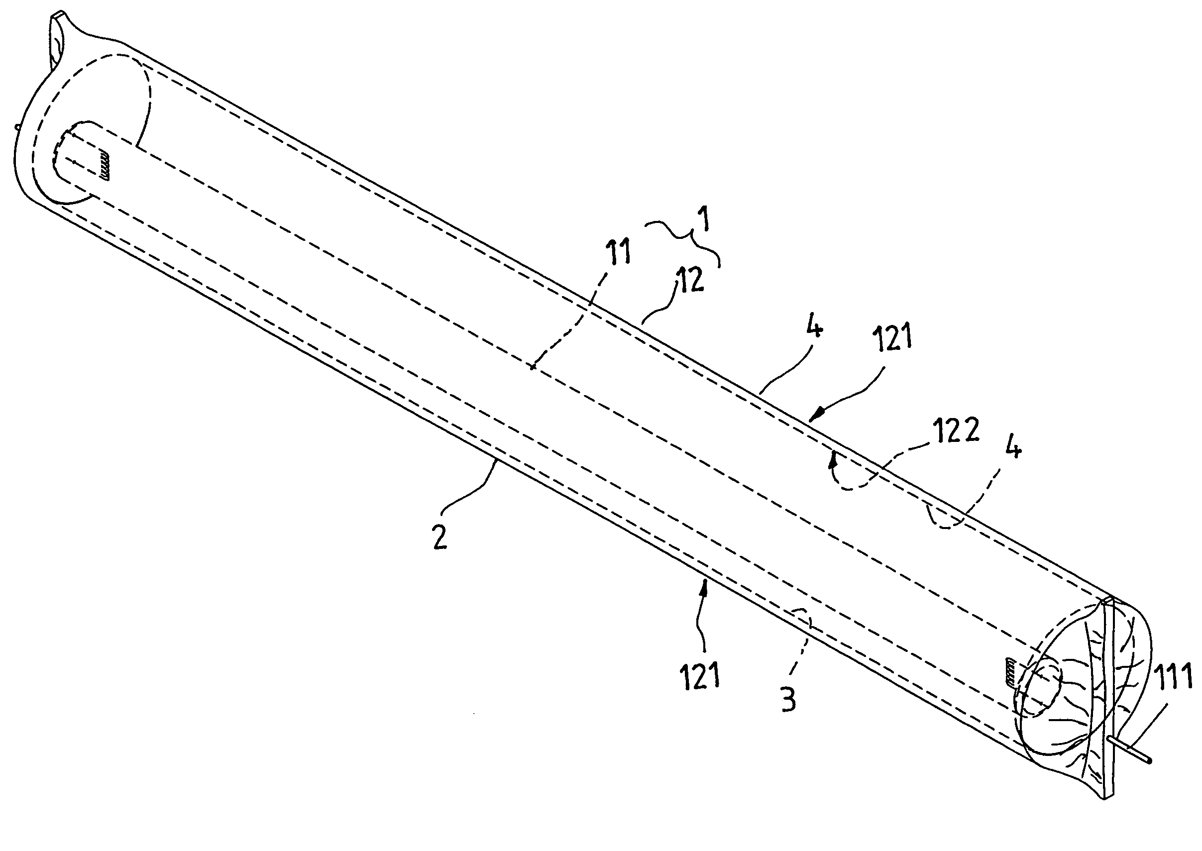
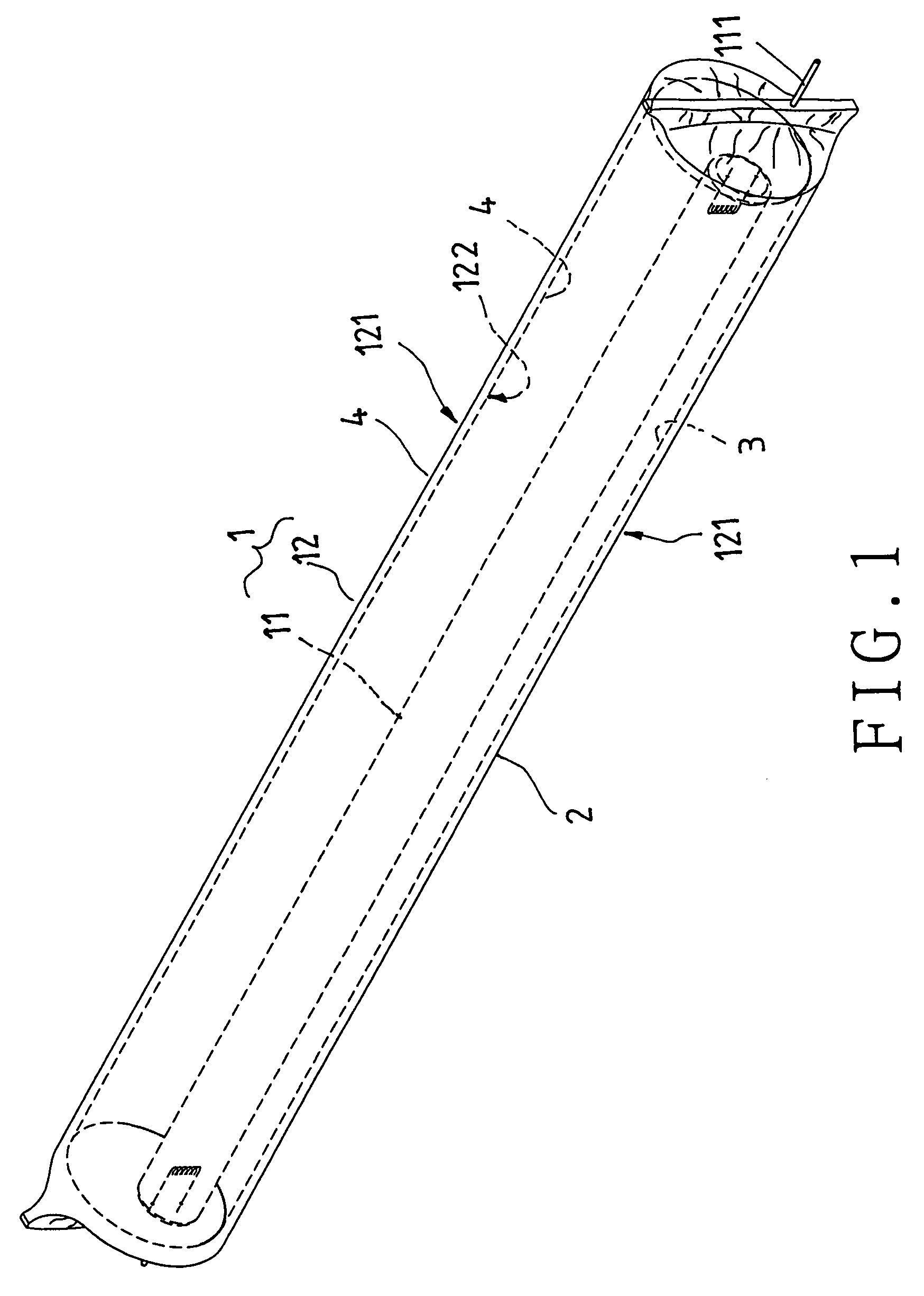
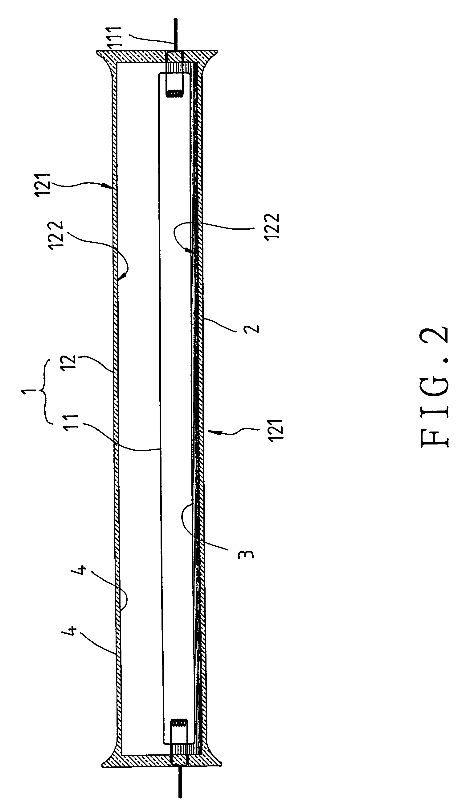
[0015]Referring to FIG. 1 to FIG. 3, a preferred embodiment of a light 1 of the present invention includes a light-producing inner tube 11, and an outer tube 12.

[0016]The light-producing inner tube 11 has electrical terminals 111 at two ends to be electrically connected to an external device in order for allowing the inner tube 11 to be powered and produce light.

[0017]The outer tube 12 is positioned around the light-producing inner tube 11 with the electrical terminals 111 of the light-producing inner tube 11 sticking out of two ends thereof. The outer tube 12 is made of a transparent material such as glass and quartz, and can be formed with a circular, olive-shaped, semicircular lateral or other-shaped section.

[0018]Furthermore, the outer tube 12 has a first portion having an outer side 121 and an inner side 122; the outer side 121 of the first portion of the outer tube 12 has a light reflecting film 2 thereon for reflecting light produced by the light-producing inner tube 11 inwar...


PUM


Abstract

A light includes a light-producing inner tube, and an outer tube positioned around the light-producing inner tube; the light-producing inner tube has electrical terminals at two ends thereof, which sticks out of the outer tube; the outer tube has a light reflecting film on an outer side of a first portion thereof; an inner side of the first portion of the outer tube is processed so as to have a rough and lumpy surface, which can cause light produce by the light-producing inner tube to travel in all directions; the outer tube has a fluorescent layer on each of inner and outer sides of a second portion thereof, which make the second portion of the outer tube more pervious to light.

Description

BACKGROUND OF THE INVENTION[0001]1. Field of the Invention[0002]The present invention relates to a light structure, more particularly one, which includes a light-producing inner tube, and an outer tube including a first portion having a relatively good light reflectivity, and a second portion having relatively good perviousness to light.[0003]2. Brief Description of the Prior Art[0004]Early electric lights usually comprise bulbs with tungsten filaments, which are gradually replaced with fluorescent lights because energy source is getting more expensive, and fluorescent lights consume less electricity than bulbs with tungsten filaments. Such a fluorescent light includes a fluorescent lamp tube capable of producing light traveling in all directions, and an external device, which is used to hold the fluorescent lamp tube in position and electrically connect the fluorescent lamp tube to a power supply, and which can reflect light produced by the fluorescent lamp tube to the area to be l...

Claims


Application Information

Patent Timeline
Patent Type & Authority Patents(United States)
IPC IPC(8): F21S4/00
CPCH01J61/025H01J61/34H01J61/70
Inventor TSAI, HUA-HSIN
Owner TSAI HUA HSIN
Learn More