
Ballistic resistant body armor articles

a technology of ballistic resistance and body armor, applied in the direction of shields, weaving, transportation and packaging, etc., can solve the problems of increasing the cost and weight of body armor, increasing the cost and weight, and reducing the flexibility of body armor

Active Publication Date: 2010-02-23
DUPONT SAFETY & CONSTR INC
View PDF68 Cites 11 Cited by
  • Summary
  • Abstract
  • Description
  • Claims
  • Application Information

AI Technical Summary

Benefits of technology

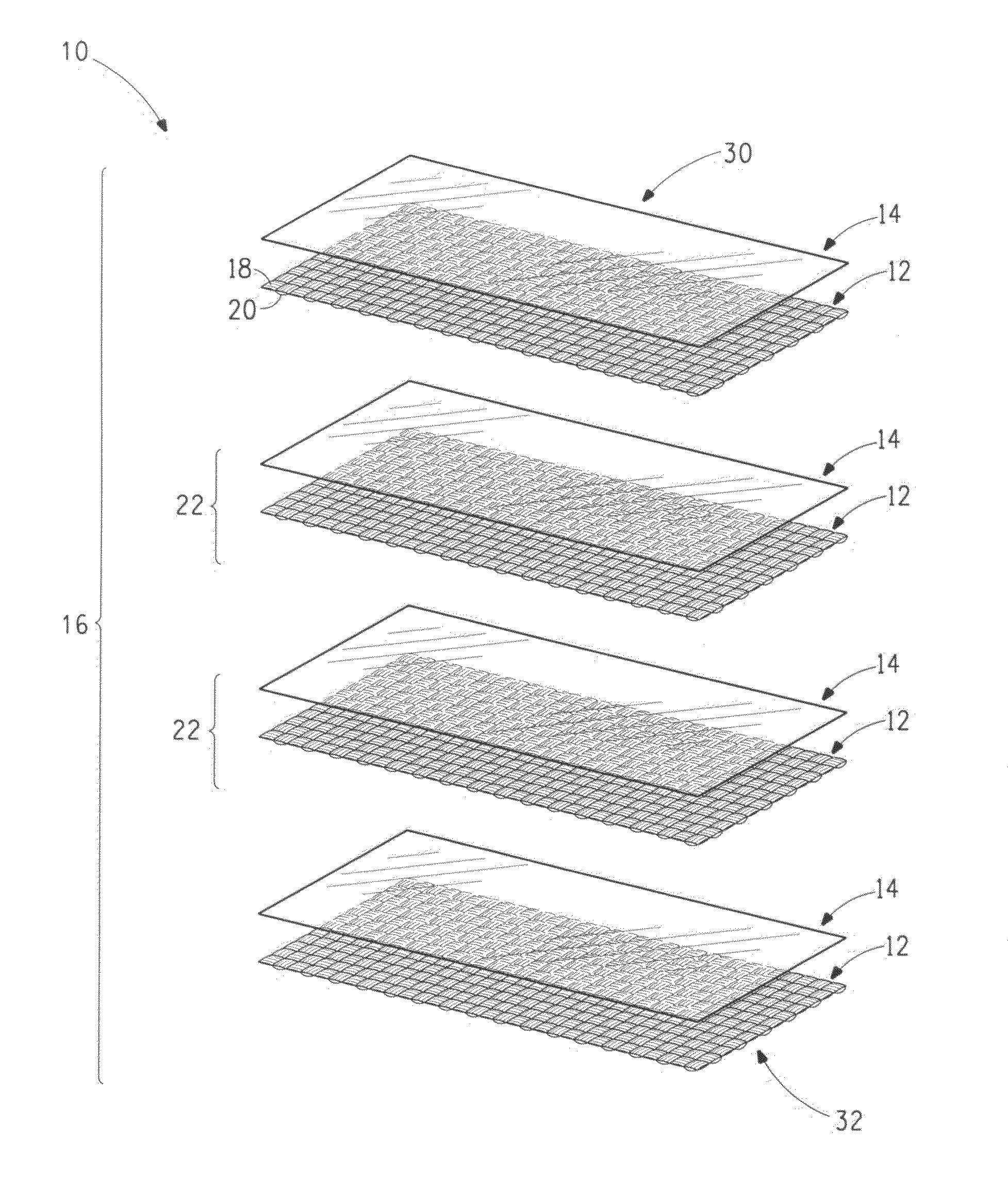
The invention is about body armor that can resist ballistic objects. It consists of multiple layers of woven fabric and sheet layers made from strong yarns and non-fibrillated fibers. These layers are stacked together to create a core section. The sheet layers make up a small percentage of the overall weight of the armor. The technical effect of this invention is to provide a strong and effective body armor that can protect against ballistic threats.

Problems solved by technology

It is also desirable to minimize the costs to make the apparel, but traditional materials used in body armor are relatively expensive.
However, increasing the margin of safety typically increases the cost and weight and decreases the flexibility of the body armor.
However, such designs typically are not optimum or even necessarily able to protect against ballistic threats.
Thus, those skilled in the art do not assume teachings on making or optimizing spike or knife resistant body armor are useful in designing ballistic resistant body armor.
However, woven fabric layers alone provide less protection against backface deformation requiring more layers and increased weight to meet the margin of safety or even the standard.
These hybrid body armors provide good penetration resistance against bullets, greater protection against backface deformation, but replacing woven fabric layers with unidirectional assemblies reduces protection against fragments, increases rigidity and increases cost.
They provide good penetration resistance against bullets, very good protection against backface deformation, but they typically provide the least protection against fragments, are more rigid than the other options, and are the most expensive.
While considered acceptable for protection against fragments, such a pulp sheet assembly does not provide protection against deformable projectiles such as a 0.44 magnum bullets that have higher impact energies.

Method used


Image

  • Ballistic resistant body armor articles
  • Ballistic resistant body armor articles
  • Ballistic resistant body armor articles

Examples


examples

[0075]The following examples are given to illustrate the invention and should not be interpreted as limiting it in any way. All parts and percentages are by weight unless otherwise indicated. Examples prepared according to the process or processes of the current invention are indicated by numerical values. Control or Comparative Examples are indicated by letters. Data and test results relating to the Comparative and Inventive Examples are shown in Tables 1 and 2.

Description of Layers

[0076]Layers of the following high tenacity fiber fabrics and nonwoven sheet structures were prepared and made into various composite assemblies for ballistic test as follows.

[0077]Fabric layer “F1” was a plain weave woven fabric of 840 denier (930 dtex) poly(p-pheynlene terephthalamide) (or PA) yarn available from E. I. du Pont de Nemours and Company under the trade name of Kevlar® para-aramid brand 129 yarn and was woven at 26×26 ends per inch (10.2×10.2 ends per centimeter).

[0078]Fabric layer “F2” was...

example a

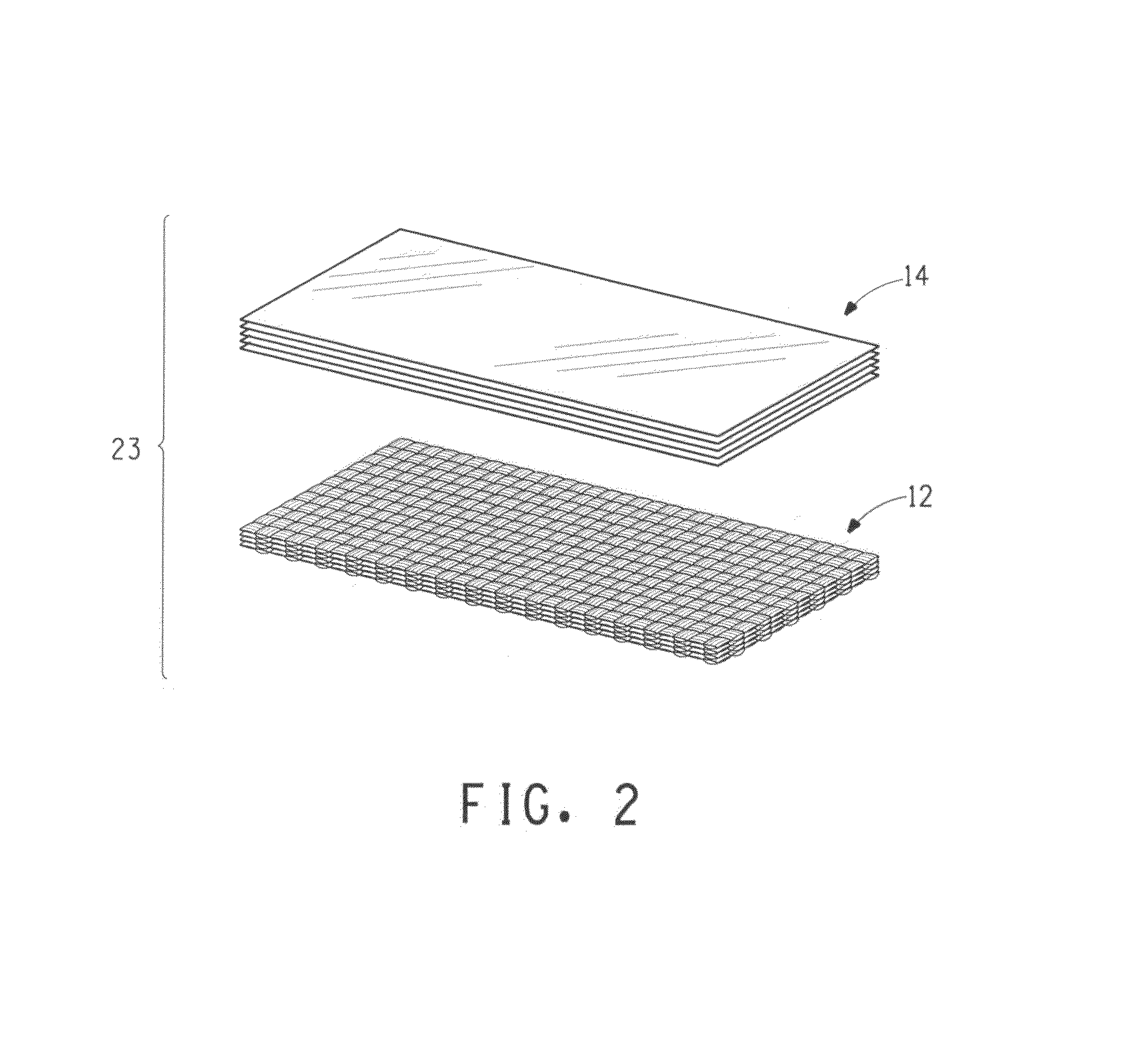
[0083]Twenty four layers of fabric layers F1 of about 15″×15″ were stitched together by stitches forming a quilted stitch pattern having a stitch spacing of about 2 inches (5 cm) and a stitch length of about 0.2 inch (0.5 cm) into an article with an areal density of about 4.73 kg / m2. Ballistic tests were conducted using 0.44 magnum bullets based on the test protocol for NIJ Level IIIA as described in NIJ Standard—0101.04 entitled “Ballistic Resistance of Personal Body Armor”. Results of the ballistic tests for eight shots, including both V50 and backface deformation, as shown in the Table 2, exhibit backface deformations as high as 61 mm but good ballistic V50.

example b

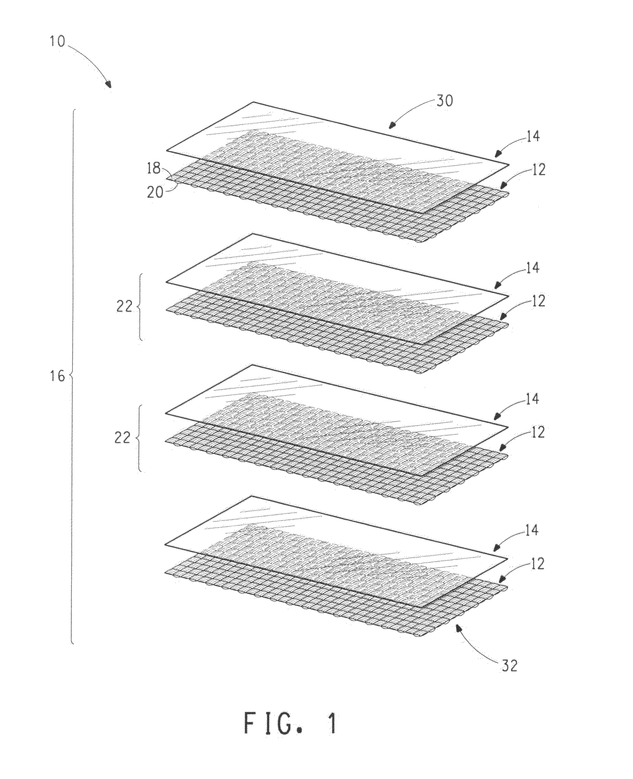
[0084]In this example, a stacked article was made comprising, in order, (a) a first strike section of 5 fabric layers F1, (b) a core section comprising a repeating unit of a fabric layer F1 then a sheet layer S1, the unit repeated 8 times, and (c) a body facing section comprising 6 fabric layers F1. This article construction is referenced herein as 5F1+8(F1+S1)+6F1. This stacked article was made of about 15 inches by 15 inches (38 cm by 38 cm) of each layer held together with stitches forming a quilted stitch pattern having a stitch spacing of about 2 inches (5 cm) and a stitch length of about 0.2 inch (0.5 cm). The areal density of the article was about 4.91 kg / m2. Ballistic tests were conducted using 0.44 magnum bullets based on the test protocol for NIJ Level IIIA as described in NIJ Standard—0101.04 entitled “Ballistic Resistance of Personal Body Armor”. Results of the ballistic tests for two shots, including both V50 and backface deformation, as shown in the Table 2, showed a b...


PUM

PropertyMeasurementUnit
weight percentaaaaaaaaaa
thicknessaaaaaaaaaa

Abstract

The present invention relates to body armor articles for resisting ballistic objects. The articles comprise woven fabric layers and sheet layers. The woven fabric layers are made from yarns having a tenacity of at least 7.3 grams per dtex and a modulus of at least 100 grams per dtex. The sheet layers comprise nonwoven random oriented fibrous sheets, each of the sheet layers comprising a uniform mixture of 3 to 60 weight percent polymeric binder and 40 to 97 weight percent non-fibrillated fibers. The woven fabric layers and the sheet layers are stacked together comprising a first core section which includes at least two repeating units of, in order, at least one of the woven fabric layers then at least one of the sheet layers. The sheet layers comprise 0.5 to 30 wt % of the total weight of the article.

Description

BACKGROUND OF THE INVENTION[0001]1. Field of the Invention[0002]This invention relates to ballistic resistant body armor.[0003]2. Description of Related Art[0004]Many designs for body armor for resisting ballistic threats have been proposed and many commercialized. Designs are made to increase comfort by the wearer to increase their use. Comfort is generally increased by making them lighter and more flexible to allow freedom of motion by the wearer. However, apparel weight needs to be increased to provide protection against projectiles with greater velocities and mass. It is also desirable to minimize the costs to make the apparel, but traditional materials used in body armor are relatively expensive.[0005]Standards have been proposed and adopted throughout the world to ensure minimum capabilities of body armor for resisting ballistic objects. See NIJ Standard—0101.04 “Ballistic Resistance of Personal Body Armor”, issued in September 2000. It defines capabilities for body armor for ...

Claims


Application Information

Patent Timeline
Patent Type & Authority Patents(United States)
IPC IPC(8): F41H1/02B32B5/12F41H5/04F41H1/00
CPCF41H1/02F41H5/0485Y10T428/24058
Inventor CARBAJAL, LEOPOLDO ALEJANDROEGRES, JR., RONALD G.
Owner DUPONT SAFETY & CONSTR INC
Learn More