Float control fluid shut off valve mechanism

a technology of safety valve and valve mechanism, which is applied in the direction of valve details, valve arrangement, thin material handling, etc., can solve the problems of uncontrollable leakage of water into the tank, easy failure of water heater or hot water tank, and easy fire extinguishing, etc., to achieve easy understanding, installation, and operation.

Inactive Publication Date: 2010-02-23
MCLEAN KERRY
View PDF20 Cites 10 Cited by
  • Summary
  • Abstract
  • Description
  • Claims
  • Application Information

AI Technical Summary

Benefits of technology

[0010]The resulting property damage is minimized due to the automatic shut off of the water supply to the water heater and to the gas supply. One advantage of the present invention is that there are no personal safety hazard concerns regarding electrical shock with water contact as this invention requires no electrical power in order to operate. Another important advantage over other devices is that the present invention performs even during a power outage. The invention is constructed of simple materials and hardware that can be found in a typical hardware store. No newly designed or manufactured valve or other major components are required except for the retainer mechanism. Standard, “off the shelf” hardware pipes, fittings, tubes, springs, floats, and valves are used in the construction of the present invention. Thus, minimal capital is required for tooling and production. The retainer mechanism is not commercially available and is manufactured from available wire.
[0011]The simplicity of the present invention is clearly an advantage over prior art devices such that a typical homeowner can easily understand, purchase, install and operate the present invention with present gas and water lines leading to gas meters, gas operated appliances and to water tanks or heaters.

Problems solved by technology

However, there may be circumstances when the burner flame is extinguished and the gas continues to escape through the pilot light into the room.
Water heaters or hot water tanks, whether in residential or commercial buildings, are susceptible to failure in a manner when the water within the tank and water entering the tank will leak uncontrollably onto the underlying floor.
Such flooding could cause extensive damage to the building and its contents particularly when the flooding occurs on a weekend in a commercial building or when the homeowner is absent from the building or house.
Because the water tank is often placed in a position remote from the water drain, serious damage can result to floors, floor coverings and to goods that are stored proximate to the leaking tank, if the tank is allowed to leak for a prolonged period of time.

Method used


Image

  • Float control fluid shut off valve mechanism
  • Float control fluid shut off valve mechanism
  • Float control fluid shut off valve mechanism

Examples


Embodiment Construction

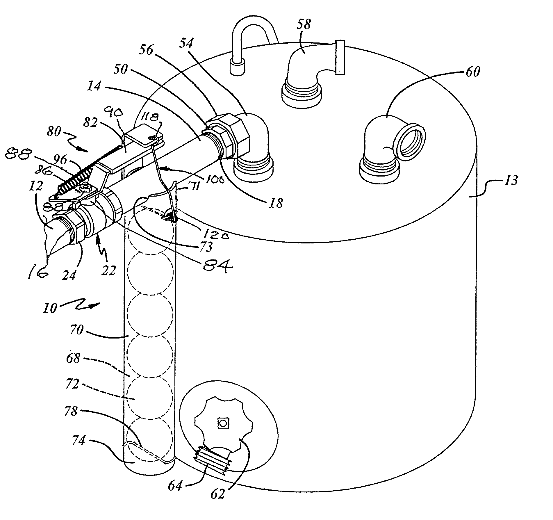
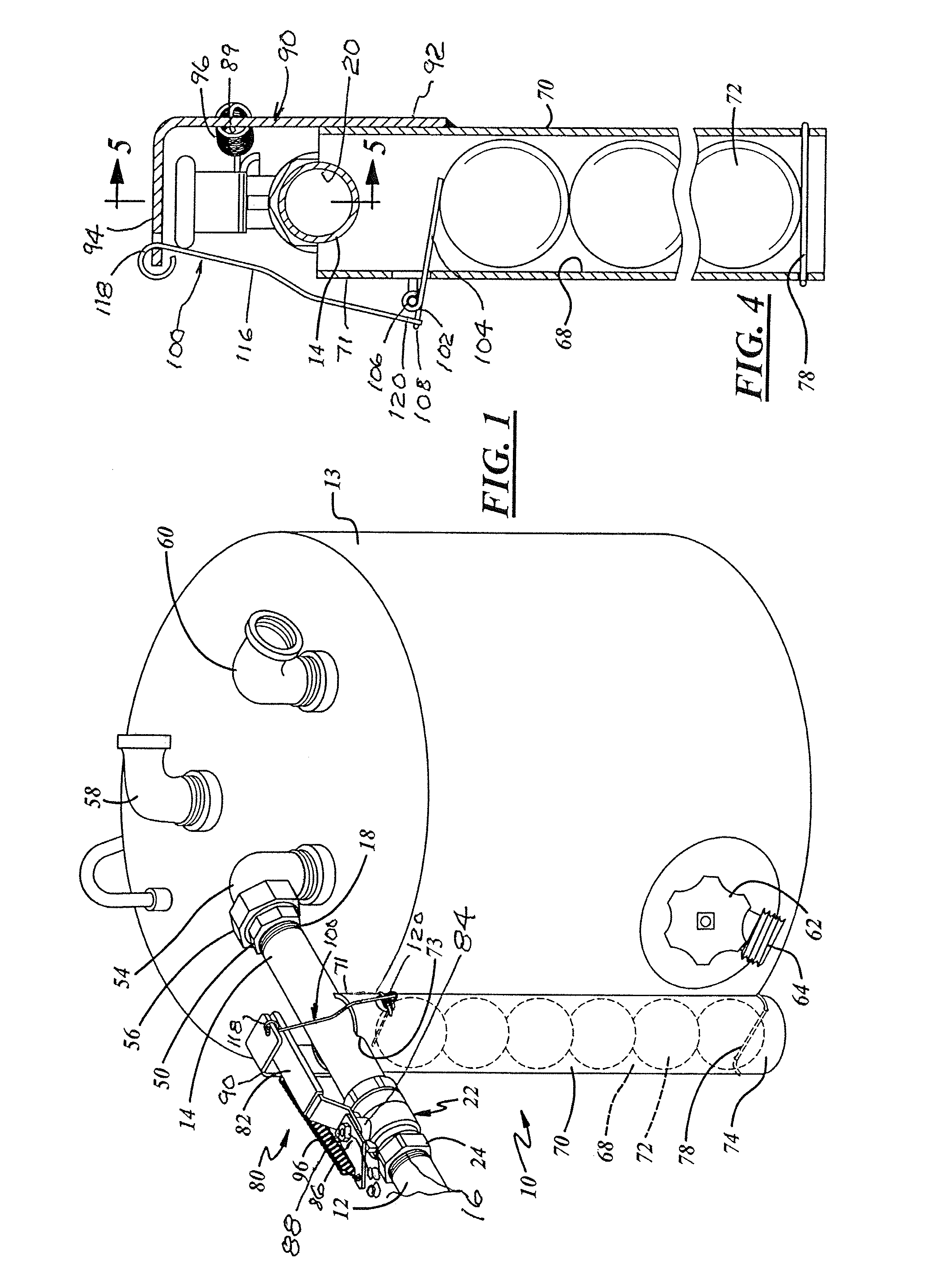
[0026]The preferred embodiment of the present invention is illustrated in FIGS. 1-8 inclusive. Other embodiments are illustrated in FIGS. 9-13 inclusive. Common to each embodiment is the use of the float control valve shut off assembly or mechanism 10, as illustrated in FIG. 1. The mechanism 10 is incorporated in the water inlet line 12 leading to a hot water tank 13 of the type that is utilized in kitchens of industrial or commercial buildings to supply hot water to the adjacent dishwasher and to a sink requiring hot water. As will be explained later, the float operated shut off valve mechanism 10 is designed for opening and closing a valve through which a fluid, either a liquid or a gas, can flow when the valve is opened.

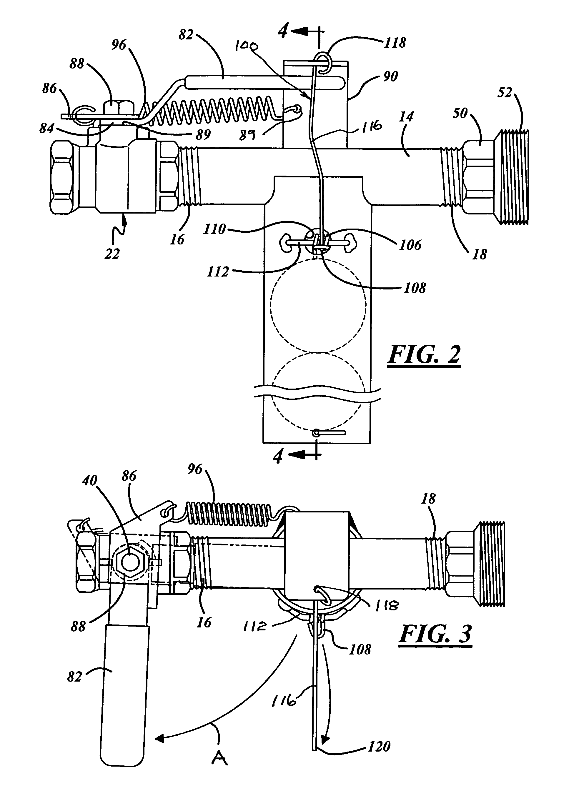
[0027]The shut off valve mechanism 10 includes a housing having an elongated pipe 14 threaded at the inlet end 16 and at the outlet end 18. The pipe 14 has a straight flow through passage 20 extending between the ends 16, 18 of the pipe 14.

[0028]A conventional bal...


PUM


Abstract

A mechanism for opening or closing a shut off valve, the mechanism having a lever mounted on a spindle to which the valve is attached for mounting the valve from a normally open position to a closed position. A trigger mechanism including the lever and a biasing spring which when activated, rotates the lever, spindle and valve. A retainer mechanism ordinarily holds the trigger mechanism in a cocked position corresponding to the open position of the valve. The float, when subjected to water, releases the retainer mechanism permitting the trigger mechanism to close the valve.

Description

TECHNICAL FIELD[0001]The present invention relates to a float control safety valve mechanism for closing fluid supply lines and, more particularly, to a shut off valve mechanism which is located in a gas line on the inlet side of a gas meter, gas dryer, gas furnace, other gas operated appliance or in a water line, as an example, on the inlet side of a hot water tank or heater. In addition, the mechanism may be interposed in any liquid line leading to a vessel or container for holding any liquid. The water or liquid escaping, as an example from a ruptured hot water tank or other vessel, is effective to operate one or more float control valve mechanisms located in the inlet line of the water tank or vessel and in the adjacent gas operated appliance where the escaping water or liquid raise the float mechanisms and closes the water and gas inlet lines.BACKGROUND OF THE INVENTION[0002]Hot water tanks are typically provided with protective devices for automatically shutting off the supply...

Claims


Application Information

Patent Timeline
Patent Type & Authority Patents(United States)
IPC IPC(8): F16K31/18
CPCF16K31/32Y10T137/7361Y10T137/7394
Inventor MCLEAN, KERRY
Owner MCLEAN KERRY
Why Eureka
Try Eureka