Blind

a technology of blinds and blind spots, applied in the field of blinds, can solve the problems of inability to make use of the device, inconvenient use, and poor appearance, and achieve the effect of improving the user experience, and improving the user experien

Active Publication Date: 2010-02-23
NICHIBEI CO LTD
View PDF24 Cites 33 Cited by
  • Summary
  • Abstract
  • Description
  • Claims
  • Application Information

AI Technical Summary

Benefits of technology

[0010]According to the invention, since the control member is wound up the pulley by the urging force of the urging member when the control member is not being operated, the control member can be kept compact and prevented from catching a passer-by, a pet animal or furniture.
[0020]Alternatively, the first clutch mechanism can comprise a switch-over guide which can turn relative to the pulley within a prescribed range of rotational angles and an engaging member which turns together with the switch-over guide and can selectively move to a position where it transmits the rotation of the pulley to the rotation shaft or to a position where it does not transmit the rotation of the pulley to the rotation shaft according to the relative turning angle between the switch-over guide and the pulley, and the switch-over guide is forbidden from turning when the rotation shaft is rotating in the other direction and turns together with the pulley when the pulley is turned by the urging member in the direction of winding up the control member. With this feature, it is possible to prevent, when the rotation shaft is rotating and the pulley is not, the switch-over guide from turning together with the rotation shaft to turn and thereby causing the first clutch mechanism to perform inadvertent switching-over to invite faulty operation.

Problems solved by technology

This configuration often confuses the user as to which direction the user should operate the control member.
Furthermore, part of the control member hung from the blind supporting member may catch a passer-by, a pet animal, furniture or the like, also may involve another problem of aesthetically poor appearance.
Japanese Examined Patent publication No. 63-46224 discloses a sheet rolling-up / down device in which the control member is compactly disposed, however none has yet been made available for practicable use.

Method used


Image

  • Blind
  • Blind
  • Blind

Examples


first embodiment

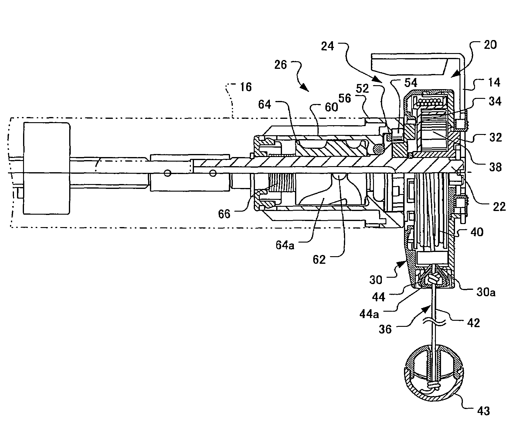
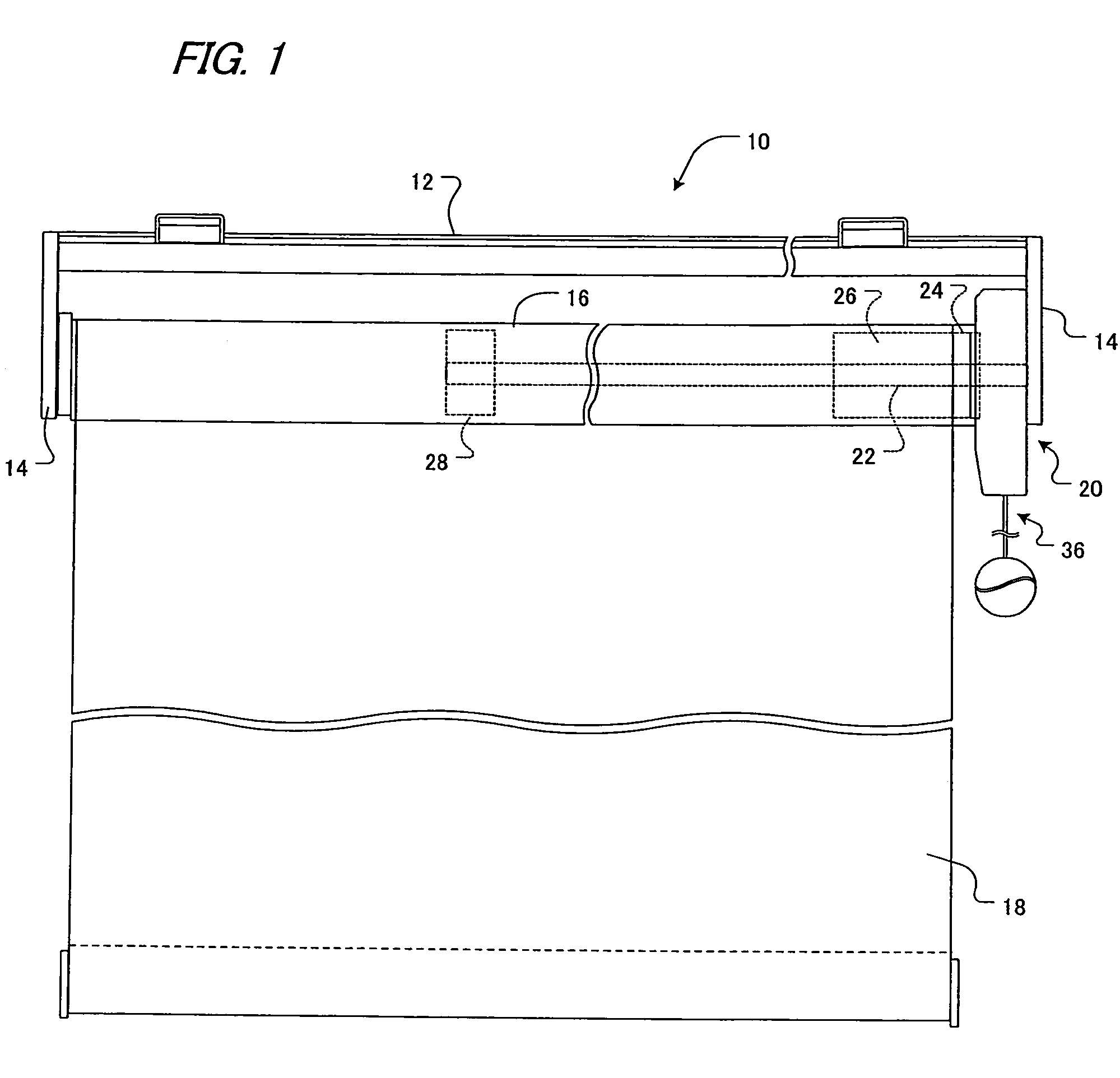
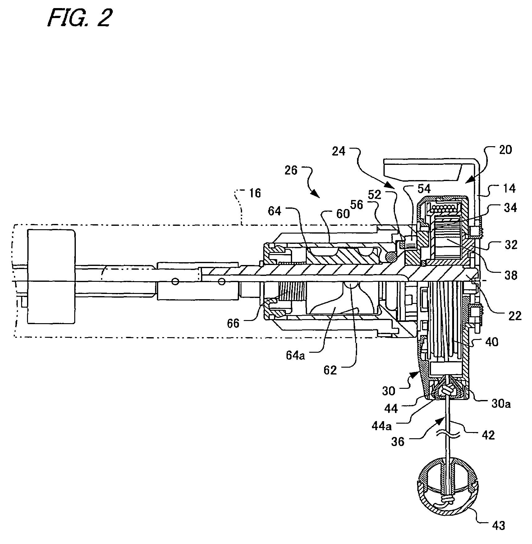
[0047]In FIG. 1, the blind is a roll screen 10 which comprises a set frame 12 fixed to a fixed surface such as a window frame or the like, a pair of supporting plates 14 fitted to respective side ends of the set frame 12, a rolling-up pipe 16 which is a rotation shaft turnably supported to the pair of supporting plates 14, a screen 18 which is a shielding member, and a control section 20 disposed between one end of the rolling-up pipe 16 and one of the supporting plates 14. One end of the screen 18 is connected to the rolling-up pipe 16, and which is hung from the rolling-up pipe 16 so as to be wound around or unwound from the rolling-up pipe 16. The one end of the rolling-up pipe 16 is supported by a supporting shaft 22 extending from the one of the supporting plates 14 into the inside of the rolling-up pipe 16. The supporting shaft 22 is basically fixed relative to the supporting plates 14, however can be turnable relative to the supporting plates 14 only when it is concurrently u...

second embodiment

[0082]FIG. 15 shows an overall front view of a second preferred embodiment of the present invention. It is different from the first embodiment wherein the screen 18 descends by its own weight when the rolling-up pipe 16 is unlinked from the supporting shaft 22 by the second clutch mechanism 26, in that a rolling-up spring 70 is arranged in the rolling-up pipe 16 to urge all the time the rolling-up pipe 16 in the direction of winding the screen. This embodiment can be accomplished by vertically inverting the guide groove 64a of the clutch drum 64 in the second clutch mechanism 26 as it is shown in the development view of the first embodiment.

[0083]In this arrangement, turning the pulley 34 to turn the rolling-up pipe 16 via the first clutch mechanism 24 allows the rolling-up pipe 16 to turn in the direction of unwinding the screen against the winding force of the rolling-up spring 70 and the screen 18 to be lowered. Also, the screen 18 can be stopped by having the second clutch mecha...

third embodiment

[0085]FIG. 16 shows a third preferred embodiment of the present invention. This embodiment constitutes an application of the invention to a horizontal blind 80, wherein many slats 82 serving as a shielding member hang from a head box 81 and are aligned vertically and supported by ladder cords 84. Further, lifting cords 88 penetrate the slats 82 and bottom ends of the lifting cords 88 are attached to a bottom rail 86 disposed underneath the slats 82. Upper ends of the ladder cords 84 and of the lifting cords 88 are connected to drums 90 disposed within the head box 81. The ladder cords 84 turn together with the drums 90 within a prescribed range of angles, and outside that range the ladder cords 84 do not turn with the drums 90. The lifting cords 88 can be wound around and unwound from the drums 90. The drums 90 are mounted on a rotation shaft 92 extending within the head box 81 in the lengthwise direction so as to unturnable relative to the rotation shaft 92. The rotation shaft 92 i...


PUM


Abstract

A blind comprises a turnably supported pulley, a control member of which one end is connected to the pulley so as to permit the control member to be wound around and unwound from the pulley, an urging member which urges the pulley in the direction of winding the control member, a first clutch mechanism which is disposed between the rotation shaft and the pulley, and can selectively link the pulley and the rotation shaft with each other to transmit the rotation of the pulley to the rotation shaft or unlink the pulley and the rotation shaft from each other to interrupt the transmission of the rotation of the pulley to the rotation shaft, and a second clutch mechanism which can selectively link the rotation shaft and a fixed member with each other or unlink them from each other.

Description

BACKGROUND OF THE INVENTION[0001]1. Field of the Invention[0002]The present invention relates to a blind in which shielding member is raised or lowered according to the turning direction of a rotatably supported rotation shaft.[0003]2. Description of the Related Art[0004]A blind is usually configured such that a shielding member is rolled up or down or shielding member is raised or lowered by winding up or down lifting cords fitted to the lower end of the shielding member in response to an operation of a control member transmitting its controlling force to a rotatably supported rotation shaft. In these cases, the rotation shaft can either directly roll or unroll the shielding member or indirectly raise or lower the shielding member by winding up or down the lifting cord.[0005]In order to ensure a sufficient operation length of the control member, which corresponds to the raising or lowering length of the shielding member, the control member is often configured in an endless form of ...

Claims


Application Information

Patent Timeline
Patent Type & Authority Patents(United States)
IPC IPC(8): E06B9/56
CPCE06B9/42E06B9/78E06B2009/905
Inventor NAOKI, TAKEBAYASHI
Owner NICHIBEI CO LTD
Why Eureka
Try Eureka