Cotton harvester row unit air sweep

a cotton harvester and air sweep technology, applied in the field of cotton harvesters, can solve the problems of common plugging still, and achieve the effects of preventing plugging, preventing blockage, and maintaining unit compactness

Inactive Publication Date: 2005-06-21
DEERE & CO
View PDF7 Cites 8 Cited by
  • Summary
  • Abstract
  • Description
  • Claims
  • Application Information

AI Technical Summary

Benefits of technology

[0005]It is another object to provide an improved air system for a cotton harvester which is particularly useful with a dual inline drum row unit for preventing blockages in wet or high yield cotton conditions.
[0006]A cotton harvester row unit having cotton discharge structure includes first and second high pressure air outlets offset in the fore-and-aft direction from each other. A first vertical tube is connected to an air supply conduit and extends downwardly and opens rearwardly near the front of the unit to direct air towards the discharge structure outlet. A second vertical tube which extends downwardly near the rear of the unit and opens towards the outlet is connected to the air supply conduit to direct a sweeping blast of air towards the outlet near the floor of the door structure where plugging is a problem. The added air blast from the second tube sweeps the floor clean near the outlet to keep material flowing into the suction door and prevent plugging. The vertical tubes can be part of the structural framework of the row unit to maintain unit compactness.

Problems solved by technology

In adverse conditions, such as in high yielding cotton or in damp cotton, plugging is still a common problem because the air stream near the rear drum is insufficient to keep the cotton moving over the floor of the door structure.

Method used


Image

  • Cotton harvester row unit air sweep
  • Cotton harvester row unit air sweep
  • Cotton harvester row unit air sweep

Examples


Embodiment Construction

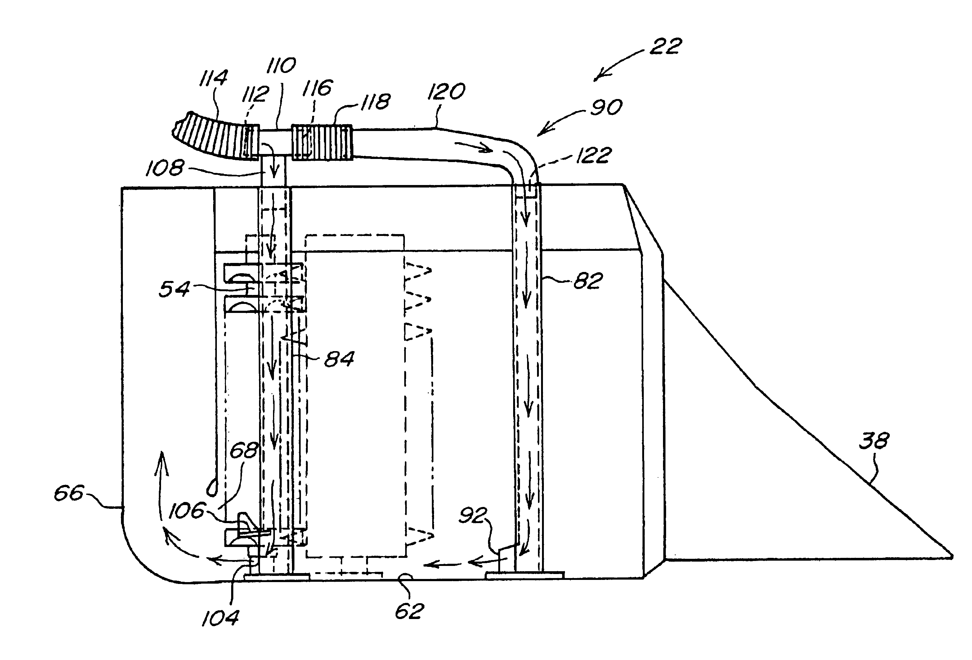
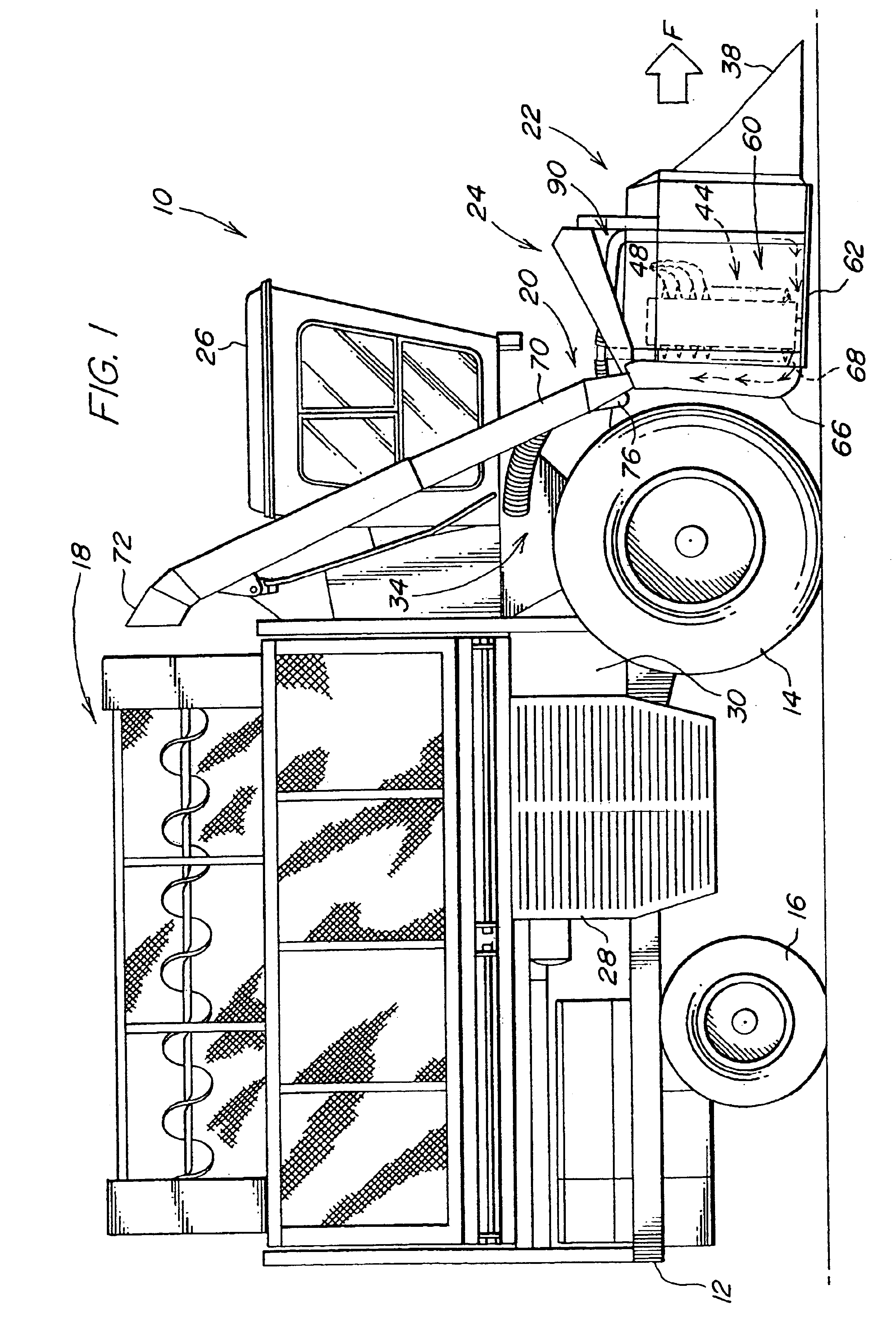
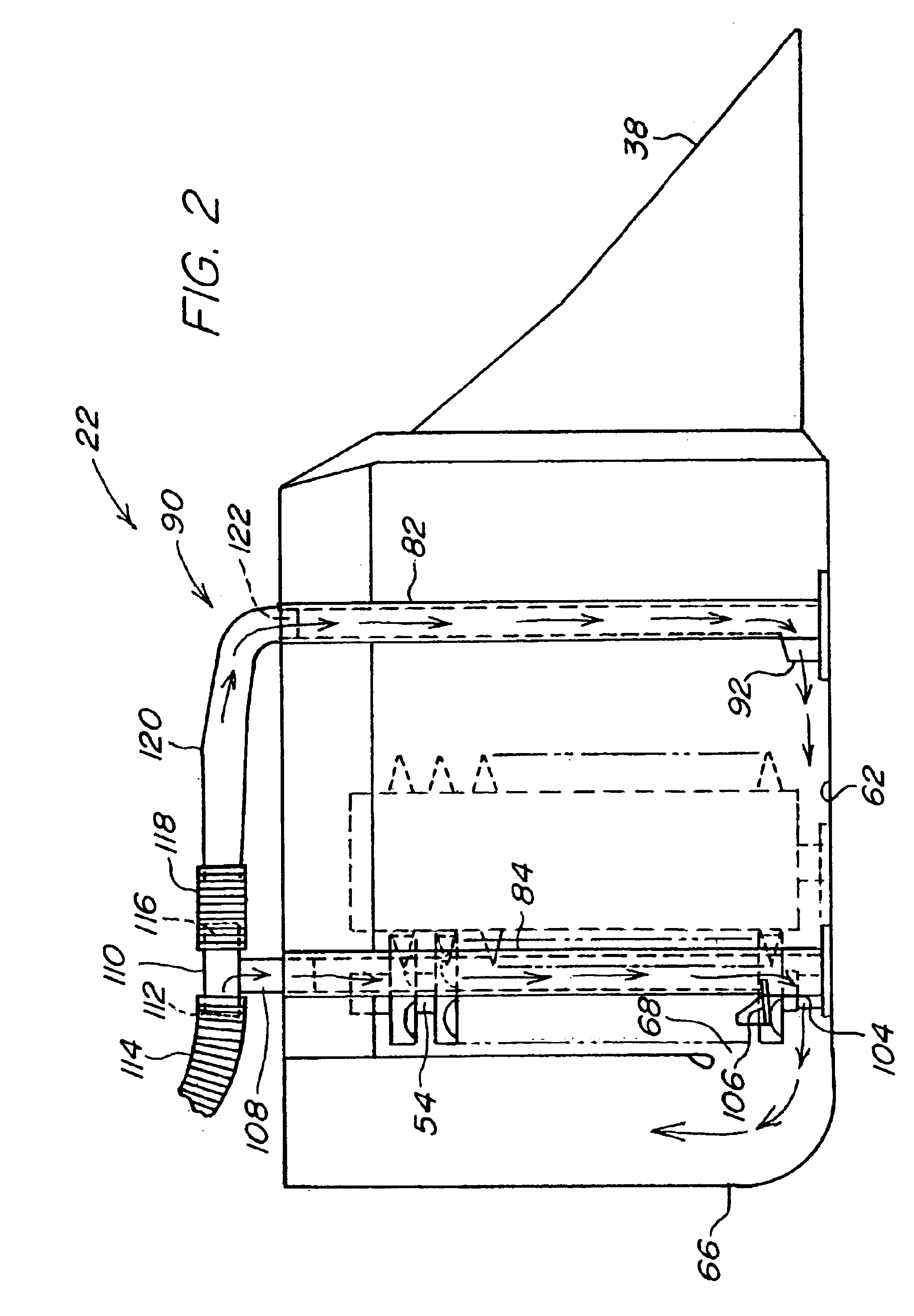
[0011]Referring now to FIG. 1, therein is shown a cotton harvester 10 generally of conventional construction and having a main frame 12 supported for forward movement over the ground by forward drive wheels 14 and rear steerable wheels 16. A cotton receptacle 18 is supported on the frame 12 for receiving cotton through an air duct conveying system indicated generally at 20. A plurality of row harvesting units 22 are transversely and adjustably spaced on vertically moveable unit support structure 24 located at the forward end of the frame 12 below an operator cab 26. An engine at location 28 powers the drive wheels 14 and fan structure 30 for supplying air to the conveying system 20 through plenum and air conduit structure 34.

[0012]Each of the row units 22 includes forward plant guide and stalk lifting members 38 directing cotton plants into a row-receiving area indicated at 40 in FIG. 3. Upright harvesting drum structures 42 and 44 located on one side of the row-receiving area 40 in...


PUM


Abstract

A cotton harvester row unit having discharge door structure includes first and second high pressure air outlets offset in the fore-and-aft direction from each other. A first vertical tube is connected to an upper air supply conduit and extends downwardly and opens rearwardly near the front of the unit to direct air towards the door structure outlet. A second vertical tube which extends downwardly near the rear of the unit and opens towards the outlet is connected to the air supply conduit to direct a sweeping blast of air towards the outlet near the floor of the door structure where plugging is a problem.

Description

FIELD OF THE INVENTION[0001]The present invention relates generally to cotton harvesters and, more specifically, to air systems for handling cotton.BACKGROUND OF THE INVENTION[0002]Jet post assemblies such as shown in U.S. Pat. No. 4,660,359 provide both structural support and an air curtain over the floor panel structure of a cotton harvester row unit discharge compartment to increase the cotton-handling capacity of the compartment and prevent clogging in damp, high yield cotton. Air is bled from a nozzle located on the cotton conveying duct and channeled through upright structural posts connected to the floor panel structure. Lower outlets in the posts direct air over the floor panel structure. The air preserves the kinetic energy of the doffed cotton and positively directs cotton to the discharge opening.[0003]Recent cotton harvesters such as exemplified in U.S. Pat. Nos. 4,821,947 and 5,519,988 include inline drum units wherein cotton removed from plants by spindles on the drums...

Claims


Application Information

Patent Timeline
Patent Type & Authority Patents(United States)
IPC IPC(8): A01D46/00A01D46/08
CPCA01D46/08
Inventor HAVERDINK, VIRGIL DEAN
Owner DEERE & CO
Why Eureka
Try Eureka