Encoder

a technology of encoder and encoder body, which is applied in the field of encoder, can solve the problems of reducing the signal detection efficiency and the signal detection efficiency of the light receiving array portion arranged in the detection head, and achieves the effects of reducing the detection accuracy, avoiding error stops, and maintaining the compact detection head

Active Publication Date: 2014-05-20
MITUTOYO CORP
View PDF29 Cites 7 Cited by
  • Summary
  • Abstract
  • Description
  • Claims
  • Application Information

AI Technical Summary

Benefits of technology

[0009]Exemplary embodiments of the invention provide an encoder in which, even in the case where contamination or the like is on a scale, or the case where a pattern on the scale is formed by an integrated pattern configured by an ABS pattern and an INC pattern, reduction of the detection accuracy can be suppressed, a detection head can be maintained compact, and an error stop can be avoided in a controlling machine to which the encoder is attached.
[0020]According to the exemplary embodiment of the invention, even in the case where contamination or the like is on a scale, or the case where a pattern on the scale is formed by an integrated pattern configured by an ABS pattern and an INC pattern, reduction of the detection accuracy can be suppressed, a detection head of an encoder can be maintained compact, and an error stop can be avoided in a controlling machine to which the encoder is attached.

Problems solved by technology

When contamination, dirt, dust, damages, or the like (hereinafter, generally referred to as contamination or the like) which may block light adheres to a scale, the signal detection efficiency of light receiving array portions arranged in a detection head is reduced, and an error occurs in a position signal indicating the position of the detection head.
Therefore, a technique is employed in which the detection area on the scale where detection is performed by the detection head is widened to reduce the percentage of the area to which dirt adheres, in the detection area, thereby lowering the rate of the reduction of the signal detection efficiency.

Method used


Image

  • Encoder
  • Encoder
  • Encoder

Examples


first embodiment

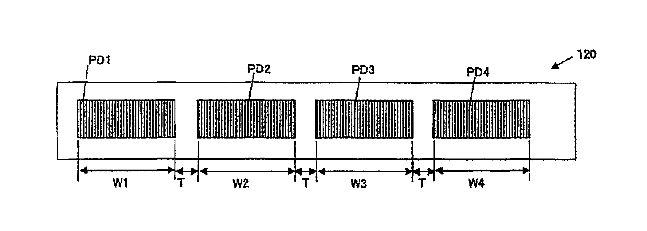
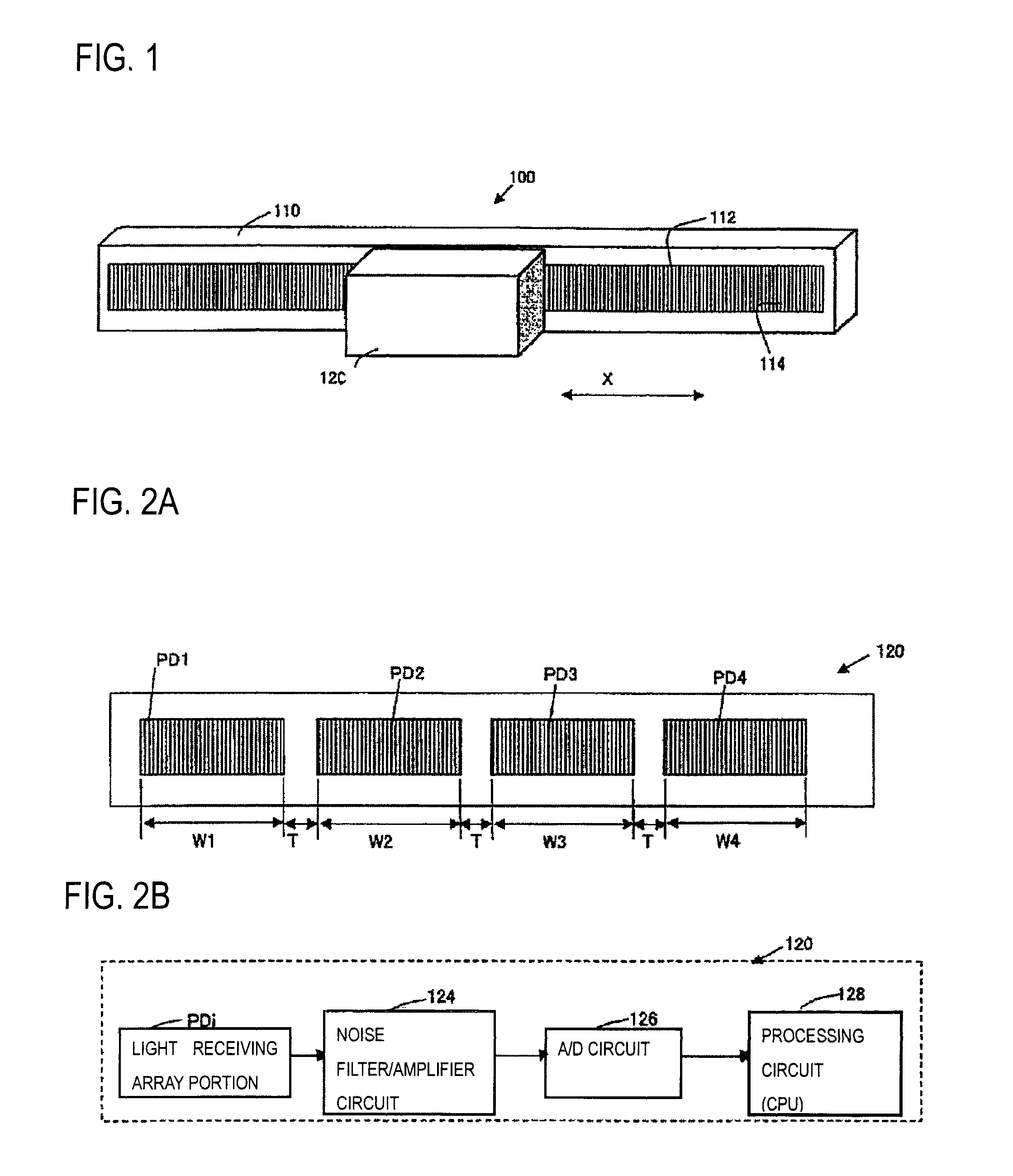
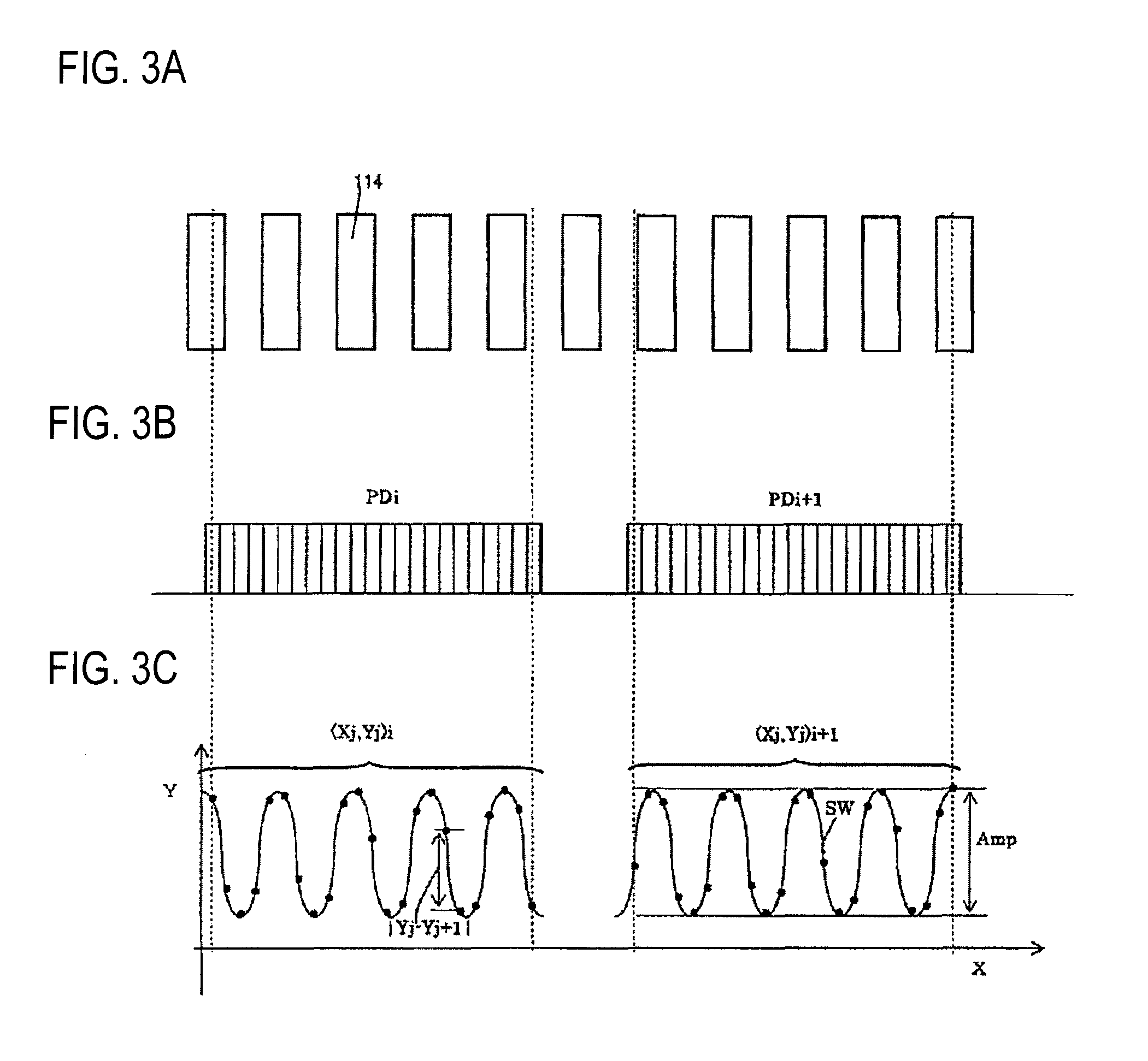
[0033]An encoder of the invention will be described with reference to FIGS. 1 to 4. FIG. 1 schematically shows the encoder 100 of the embodiment, FIG. 2A shows arrangement of light receiving array portions PDi (in the figure, i=1 to 4) in a surface of a detection head 120 which is opposed to a track 112, FIG. 2B is a block diagram of the detection head 120, FIG. 3A shows arrangement of optical gratings 114 constituting the track 112, FIG. 3B shows light receiving array portions PDi, PDi+1 opposed to the track 112, FIG. 3C shows signal strengths (each indicated by a solid circle) which are output from individual light receiving elements constituting the light receiving array portions PDi, PDi+1, and a curve SW which is obtained by using the sinusoidal curve fitting, and the like, and FIG. 4 is a diagram showing relationships between the scale and the light receiving array portions in the case where contamination or the like is on the scale.

[0034]First, the configuration of the encode...

third embodiment

[0060]Alternatively, the invention may be configured as a third embodiment which will be described below. In the embodiment, Expression (5) is used as the reliability coefficient Ri. In the embodiment, a conventional two-phase sinusoidal signal is used as the output signal obtained in the processing circuit 128. In the light receiving array portion PDi, light receiving elements are arranged so as to produce outputs which are different in phase by 90 degrees from each other. Then, the product of the array width Wi of the light receiving array portion PDi, and the diameter ri of a Lissajous waveform Lsj of FIG. 5 which is obtained from the two-phase sinusoidal signal that is an output signal output from the light receiving array portion PDi is set as the reliability coefficient Ri.

[Exp. 5]

Ri=Wi*ri  (5)

[0061]In the embodiment, therefore, the reliability of the position signal xi is high when the diameter ri of the Lissajous waveform Lsj is large and the array width Wi is large, and hen...

fourth embodiment

[0062]In the above-described embodiments, the invention is applied to an INC pattern in which optical gratings are arranged at regular intervals. The invention is not limited to this. The invention particularly exerts the effects in the case where a periodical output signal can be obtained from the light receiving array portions PDi such as the case where the invention is applied to the INC pattern of the scale 110, or namely the case where a track on a scale has optical gratings which are arranged at constant intervals (the track has an INC component). Therefore, any of the relationships indicated by Expressions (2) to (5) can be applied to an integrated pattern 213 which is shown in a fourth embodiment shown in FIG. 6, and which is configured by an ABS pattern based on a pseudorandom code, and an INC pattern (FIG. 6 of JP-A-2009-2702). Also with respect to the integrated pattern, reduction of the detection accuracy can be suppressed, the detection head can be maintained compact, a...


PUM


Abstract

A detection head includes a plurality of detection array portions that are arranged in a direction along which the head is relatively displaceable. Position signals indicating a position of the detection head are calculated from output signals output from the detection array portions. In order to combine the position signals with one another and determine the position of the detection head with respect to the scale, weighting according to a level of the output signal is performed on the position signal of each of the detection array portions, and the weighted position signals are averaged.

Description

CROSS REFERENCE TO RELATED APPLICATION(S)[0001]This application is based upon and claims the benefit of priority from Japanese Patent Application No. 2010-228310 filed on Oct. 8, 2010, the entire contents of which are incorporated herein by reference.TECHNICAL FIELD[0002]The present invention relates to an encoder including a scale and a detection head which is relatively displaceable with respect to the scale.RELATED ART[0003]An encoder including a scale and a detection head which is relatively displaceable with respect to the scale is used for accurately performing position control on a controlling machine to which the encoder is attached. A photoelectric encoder will be exemplarily described. When contamination, dirt, dust, damages, or the like (hereinafter, generally referred to as contamination or the like) which may block light adheres to a scale, the signal detection efficiency of light receiving array portions arranged in a detection head is reduced, and an error occurs in a...

Claims


Application Information

Patent Timeline
Patent Type & Authority Patents(United States)
IPC IPC(8): G01D5/36G01D5/347
CPCG01D5/24476
Inventor KATO, YOSHIAKI
Owner MITUTOYO CORP
Why Eureka
Try Eureka