Method and apparatus for controlling peripheral image position for reducing progression of myopia

a peripheral image position and control method technology, applied in the field of methods and systems for the treatment of can solve the problems of poor compliance of wearers to maintain this method of treatment, inability to achieve constant blurred vision, and poor central vision, so as to reduce or cease the progression of refractive error, good central vision, good effect of useful vision

Active Publication Date: 2010-02-23
BRIEN HOLDEN VISION INST (AU)
View PDF12 Cites 84 Cited by
  • Summary
  • Abstract
  • Description
  • Claims
  • Application Information

AI Technical Summary

Benefits of technology

[0034]Embodiments of the present generally relate to methods and devices for the retardation or cessation of refractive error progression. The over-arching approach involves 1) the repositioning of the peripheral image to provide stimulus to retard or eliminate the progression of myopia or hyperopia and 2) maintaining good central vision by positioning the central image on or near the fovea / retina, while 3) substantially simultaneously providing one or more vision priority zones, for select visual directions, with controlled or reduced defocus and / or other optical aberrations to provide good, useful vision at those select directions. The devices for the delivery of this method may include, but are not limited to, spectacles, contact lenses (including those used for orthokeratology, corneal on-lays, corneal in-lays, anterior chamber lenses, intra-ocular lenses), etc. Preferred methods may involve techniques including but not limited to corneal refractive surgery (e.g. photorefractive keratectomy, LASIK, LASEK), orthokeratology, etc.
[0035]An embodiment of the invention relates to a method of retarding the progression of myopia by providing to the eye a stimulus to retard or cease the progression of myopia by repositioning the peripheral visual image (from off-axis visual object points when the eye is in the straight-ahead viewing direction of gaze) so that at least the more anterior of the two image surfaces associated with astigmatism is positioned on, or anterior to, the retina, while substantially simultaneously providing good central vision to the eye by positioning the central visual image (from on-axis visual object points when the eye is in the straight-ahead viewing direction of gaze) so that the image lies near to or on the fovea of the eye; and also substantially simultaneously providing one or more vision priority zones corresponding to select directions of fixation for the eye, for which other optical aberrations and / or defocus is controlled or reduced to provide to the eye good, useful vision along those select directions of fixation.
[0041]Given the foregoing, it will be clear that multifunctional devices may be constructed involving combinations of vision priority zones of different configurations that are incorporated in the one vision treatment device to accompany the underlying vision treatment zone, in order to reduce or cease the progression of refractive error, provide good central vision and provide good, useful vision through select vision priority zones.
[0042]It will also be clear from the foregoing that the method may be applied to retarding the progression of hyperopia by providing to the eye a stimulus to retard or cease the progression of hyperopia by repositioning the peripheral visual image (from off-axis visual object points when the eye is in the straight-ahead viewing direction of gaze) so that at least the more posterior of the two image surfaces associated with astigmatism is positioned on or posterior to the retina, while simultaneously providing good central vision to the eye by positioning the central visual image (from on-axis visual object points when the eye is in the straight-ahead viewing direction of gaze) so that the image lies near to or on the fovea of the eye, and also simultaneously providing one or more vision priority zones corresponding to select directions of fixation for the eye for which other optical aberrations and / or defocus is controlled or reduced to provide to the eye good or useful vision along those select directions of fixation.

Problems solved by technology

Since the position of the visual image is not relocated to the retina, constant blurred vision is an implicit and undesirable consequence of the under-correction method.
Due to the constant blurred vision, compliance of the wearer to maintain this method of treatment is likely to be poor.
However, studies on the efficacy of methods that employ bifocal devices generally show only limited efficacy.
In the case of bifocal or progressive spectacles, compliance of the wearer to always look through the near addition portion of the spectacles for near work cannot be guaranteed.
Such bifocals degrade the overall retinal image quality and are known to produce undesirable visual problems such as haloes, glare and ghosting.
In at least some of the on-axis optical methods described (for example, the induction of positive spherical aberration), the method necessarily implicitly degrades the visual acuity and could lead to poor compliance on the part of the patient and would therefore suffer the same disadvantages as under-correction methods.
Since most conventional optical vision correction devices have typically only two (one anterior, one posterior) optical surfaces, when the lens is designed to manipulate relative curvature of field, due to the limited number of design parameters (e.g. lens surface shape, refractive index of material, lens thickness, distance from the pupil, etc) limiting the degrees of freedom in optical design, some other optical aberrations may be concomitantly introduced or altered.
For centered vision correction devices, undesirable other optical aberrations may arise through the portion of the optical device that corresponds to the off-axis directions or peripheral fields in the manner described above.
Such an image will incur and suffer from the other optical aberrations produced by the peripheral portion of the device.
In addition to the undesirable other optical aberrations produced by the peripheral portion of the device, decenterable vision correction devices that employ the myopia treatment method as taught by U.S. Pat. No. 7,025,460 can also suffer from blurring due to defocus during eccentric gaze.
Thus, when the eye is directed to fixate on a peripheral visual object through a decenterable visual correction device, the image is blurred due to both defocus and other optical aberrations.

Method used


Image

  • Method and apparatus for controlling peripheral image position for reducing progression of myopia
  • Method and apparatus for controlling peripheral image position for reducing progression of myopia
  • Method and apparatus for controlling peripheral image position for reducing progression of myopia

Examples


Embodiment Construction

[0069]For the wearers, such as those described in the previous sections, who require good central vision as well as certain select other directions of gaze, it would be beneficial and advantageous to provide a vision treatment device that can impart the refractive error-reducing stimulus through the appropriate manipulation of the position of the peripheral image points as taught by U.S. Pat. No. 7,025,460, but for which other optical aberrations are reduced for those select directions of gaze—i.e. for the vision priority zones. In addition, should the vision treatment devices be of the decenterable type, it would be beneficial and advantageous to not only control or reduce the other optical aberrations through the select directions of gaze but also to control or reduce defocus.

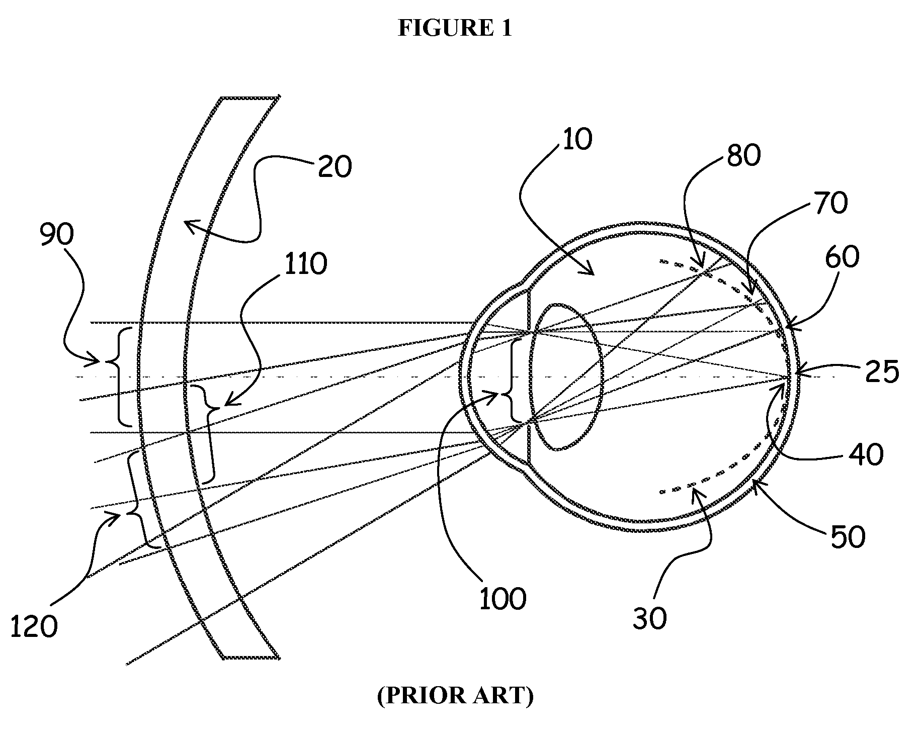
[0070]FIG. 1 explains the rationale pertaining to the control of other optical aberrations behind the current invention. In FIG. 1, an eye 10, with myopic tendencies (i.e. is either myopic or would develop my...


PUM


Abstract

A method and apparatus are disclosed for controlling optical aberrations to alter relative curvature of field by providing optical devices and methods comprising the repositioning of peripheral off-axis focal points relative to the retina to produce stimulus for influencing the progression of refractive error while simultaneously controlling the position of the central focal point near to the retina to provide clear central vision and simultaneously providing zones of controlled peripheral defocus and other optical aberrations to improve peripheral vision for select directions of gaze.

Description

CROSS-REFERENCE[0001]This application claims benefit of priority from co-pending and commonly assigned U.S. Provisional Patent Application Nos. 60 / 758,316 filed Jan. 12, 2006 and 60 / 782,658 filed Mar. 15, 2006.FIELD OF THE INVENTION[0002]The present application is directed generally to methods and systems for the treatment of progression of refractive error. It represents a novel and unobvious advance over commonly assigned U.S. Pat. No. 7,025,460.[0003]In particular, the present invention is directed to methods, systems and apparatuses for retarding or eliminating the progression of myopia in an individual by controlling off-axis aberrations, thereby manipulating the relative curvature of field of a visual image while simultaneously providing clear imaging at select non-central directions and points of vision.[0004]Myopia, also known as shortsightedness or nearsightedness, is a type of refractive error of the eye. Refractive error, an optical state of the eye in which the focus of ...

Claims


Application Information

Patent Timeline
Patent Type & Authority Patents(United States)
IPC IPC(8): G02C7/02A61B3/10
CPCG02C7/02G02C7/047A61F9/008A61F2009/00872G02C2202/24A61F9/013
Inventor HO, ARTHURSMITH, III, EARL LEOSANKARIDURG, PADMAJAHOLDEN, BRIEN ANTHONY
Owner BRIEN HOLDEN VISION INST (AU)
Why Eureka
Try Eureka