Mounting clip

a technology of mounting clips and clips, which is applied in the field of mounting clips, can solve the problems of oversized apertures, and achieve the effects of low deformation forces, large dimensional deviations, and high deformation resistan

Inactive Publication Date: 2010-03-02
NEWFREY
View PDF36 Cites 30 Cited by
  • Summary
  • Abstract
  • Description
  • Claims
  • Application Information

AI Technical Summary

Benefits of technology

[0006]The object of the invention is to further develop a mounting clip of the aforementioned type such that it can be used in both precisely fitting and less precisely fitting apertures in a supporting part, and that guarantees secure seating of the mounting clip without play, even in less precisely fitting apertures. In addition, the mounting clip should be easy and economical to manufacture.
[0008]As a result of the inventive design, the mounting clip is supported in the aperture of the supporting part not only by the latching fingers which engage in the aperture and rest against the underside of the supporting part, but also is supported on the supporting part, perpendicular to the direction of action of the latching fingers, by a contact surface on the shank section and an elastic rib or tongue. In this context, the contact surface ensures a defined orientation of the mounting clip in the aperture, while the elastically resilient rib or tongue braces the mounting clip in the aperture, even if the aperture is oversized to a certain extent. In this way, the requirements for manufacturing precision in the production of the aperture in the supporting part can be reduced, and larger manufacturing tolerances can be permitted, without thereby impairing the seating of the mounting clip. Moreover, the aperture can be oversized to a certain extent from the beginning, making it easier to install the mounting clip. In addition, if suitably designed, the mounting clip can be used for multiple aperture sizes, for example slot sizes or round hole sizes.
[0009]According to another proposal of the invention, the shank section has two essentially parallel legs, which are joined together by the head section on the one hand, and by at least one connecting web on the other hand, wherein between the legs is an open space in which is arranged the elastically resilient rib or tongue. This design of the mounting clip has the advantage that a simple, two-part mold can be used to manufacture it as an injection molded plastic part. As a result, the mounting clip can be produced very economically.
[0012]Another advantageous embodiment can consist in that an elastically resilient tongue is molded on a connecting web, which tongue extends toward the head section and has a free end that is adjacent to the head section and is arranged on the outer side and a distance apart from the lateral terminating plane of the shank section. In this embodiment, the elastically resilient tongue has a relatively great length, so that large dimensional deviations can be compensated for with relatively low deformation forces.
[0013]In a different embodiment, provision can also be made for the elastically resilient rib to be molded with one end on a connecting web and the other end on the head section, and to have a middle region that is arranged on the outer side and a distance apart from the lateral terminating plane of the shank section. This design permits a higher deformation resistance, but with somewhat reduced tolerance compensation. Here, too, the projecting middle region can be composed of a convex curvature of the tongue.
[0014]For attaching a component to the head section, said head section can be provided with various retaining elements, for example a hooked or T-shaped retaining element. Moreover, it is possible to arrange elastic tabs on the head section which comprise a resilient brace for the supporting part and have the effect that the supporting part can be clamped between the elastic tabs resting against the top surface and the latching fingers resting against the underside once the mounting clip has been inserted.

Problems solved by technology

Moreover, the aperture can be oversized to a certain extent from the beginning, making it easier to install the mounting clip.

Method used


Image

  • Mounting clip
  • Mounting clip
  • Mounting clip

Examples


Embodiment Construction

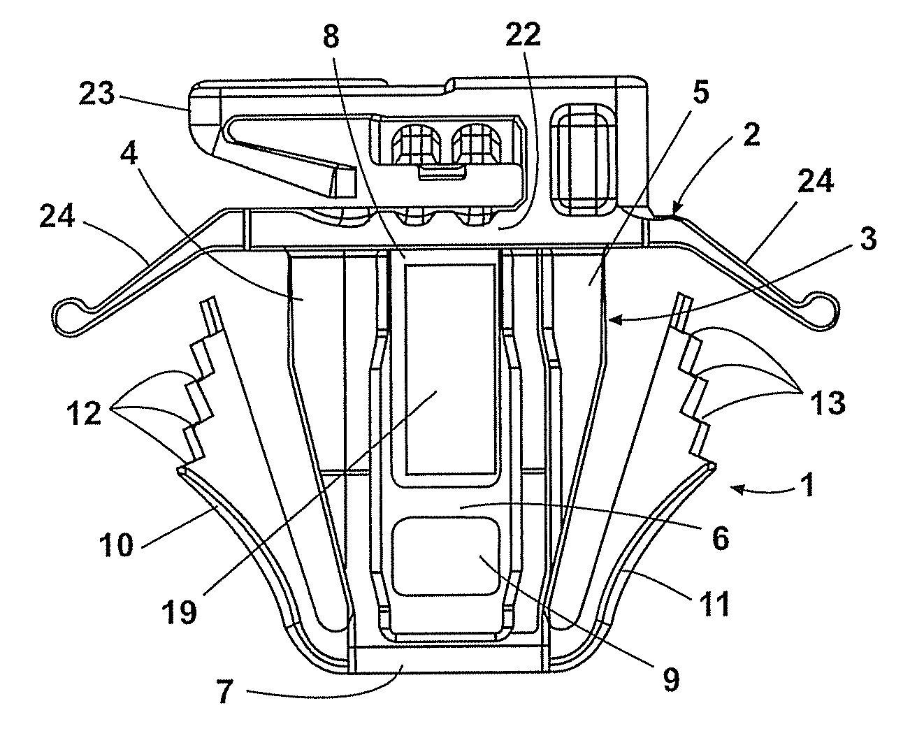
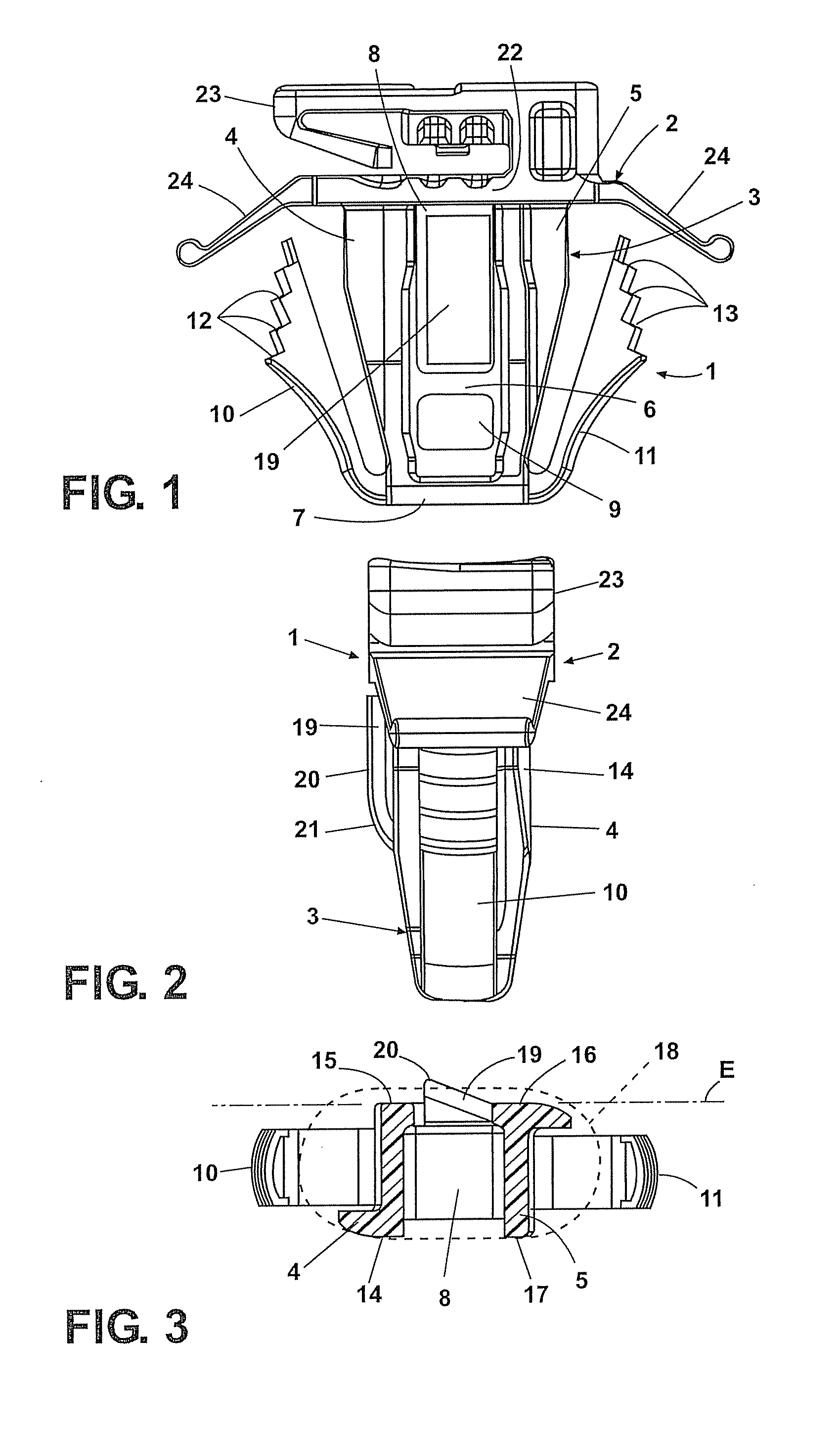
[0023]The mounting clip 1 shown in FIGS. 1 through 3 is a one-piece plastic part which can be manufactured in the injection molding process using a two-part mold. The mounting clip 1 has a head section 2 and a shank section 3, which is composed of two legs 4, 5, which are essentially parallel to a central clip axis, and connecting webs 6, 7 arranged between said legs. Located between the legs 4, 5 are through-apertures 8, 9, which are separated from one another by the connecting web 6. Arranged at the level of the connecting web 7, on the narrow sides of the shank section 3 facing away from one another, are latching fingers 10, 11, which extend outward at an angle with respect to the clip axis, and extend toward the head section. The mounting ends of the latching fingers 10, 11 are elastically deformable so that the free ends of the latching fingers 10, 11 can be moved until they contact the legs 4, 5. At each of their free ends, the latching fingers 10, 11 have four latching surfac...


PUM


Abstract

A mounting clip for mounting a component on a supporting part having an aperture includes a head section for attaching the component. A shank section is insertable in the aperture. At least two latching fingers are resiliently held apart from the head section on opposite shank section sides which spread outward toward the head section. At free ends the latching fingers have latching surfaces that rest against a supporting part underside when the mounting clip is inserted in the aperture. The shank section has on one side which extends perpendicular to the sides having the latching fingers, a contact surface that is supported on the aperture inner edge, and has on the side opposite the contact surface an elastically resilient rib or tongue that is supported with a preload against the aperture inner edge after the mounting clip is placed in the aperture.

Description

CROSS-REFERENCE TO RELATED APPLICATIONS[0001]This application claims the benefit of German Patent Application No. 10 2006 017 878.5, filed Apr. 13, 2006. The disclosure of the above application is incorporated herein by reference.FIELD[0002]The invention concerns a mounting clip for mounting a component on a supporting part provided with an aperture, comprising a head section for attaching the component, a shank section that can be inserted in the aperture, and at least two latching fingers, which are resiliently held at a distance from the head section on opposite sides of the shank section and which extend outward, at an angle with respect to the clip axis, and toward the head section, and which have, at their free ends, latching surfaces that rest against the underside of the supporting part after the mounting clip has been inserted in the aperture thereof, in order to secure the mounting clip in the aperture in this way.BACKGROUND[0003]Mounting clips of the specified type are of...

Claims


Application Information

Patent Timeline
Patent Type & Authority Patents(United States)
IPC IPC(8): F16B15/00F16B45/00
CPCB60R11/00B60R13/0206F16B21/086F16B5/0621B60R2011/0059B60R2011/0071Y10T403/606Y10T403/7176Y10T24/309Y10T24/42
Inventor STIGLER, MARIOSENG, HANS PETER
Owner NEWFREY
Why Eureka
Try Eureka