Magnet holder

a technology of magnet holder and holder, which is applied in the field of magnet holder, can solve the problems of considerable increase in the mass and cost of such a holder, and achieve the effects of high adhesive friction, simple mounting and handling, and simple handling

Active Publication Date: 2006-08-31
TUNZE AQUARIENTECHN
View PDF16 Cites 18 Cited by
  • Summary
  • Abstract
  • Description
  • Claims
  • Application Information

AI Technical Summary

Benefits of technology

[0013] The further developments of the invention wherein the edge contour of the flux-conducting arms is a dumbbell shape and that end sections of the flux-conducting arms and the permanent magnets have substantially identical edge geometry, are of advantage from the point of view of a further improvement in twist-proofing and a magnetic self-centering of the parts of the holder on one another.
[0014] The further development of the invention wherein the flux-conducting arms are connected via a connecting section to form a one-piece unit, is of advantage from the point of view of simple mounting and handling of the flux-conducting arms.
[0015] The further development of the invention wherein the flux-conducting arms are disposed on a transparent holding plate also promotes simple handling of the holder on attachment and removal. In addition, a larger part of the pane remains visible.
[0016] The further development of the invention wherein the holding plate is provided on the side that faces toward the panes with a contact layer having high adhesive friction and / or adhesive cups promotes a further improvement in the frictional-contact connection to the pane.
[0017] In this connection, the configuration of the layer having high adhesive friction wherein the contact layer is manufactured from transparent elastomeric material, once again, is of advantage from the point of view of an attractive exterior of the holder when mounted.

Problems solved by technology

If it were desired, even in the case of a glass face which is not clean and is immersed in liquid, to obtain equally secure seating using only magnetic forces, it would be necessary to choose a very large magnet arrangement, which is disadvantageous from the aesthetic point of view.
Also, the costs of such a holder and its mass would be considerably increased.

Method used


Image

  • Magnet holder
  • Magnet holder
  • Magnet holder

Examples


Embodiment Construction

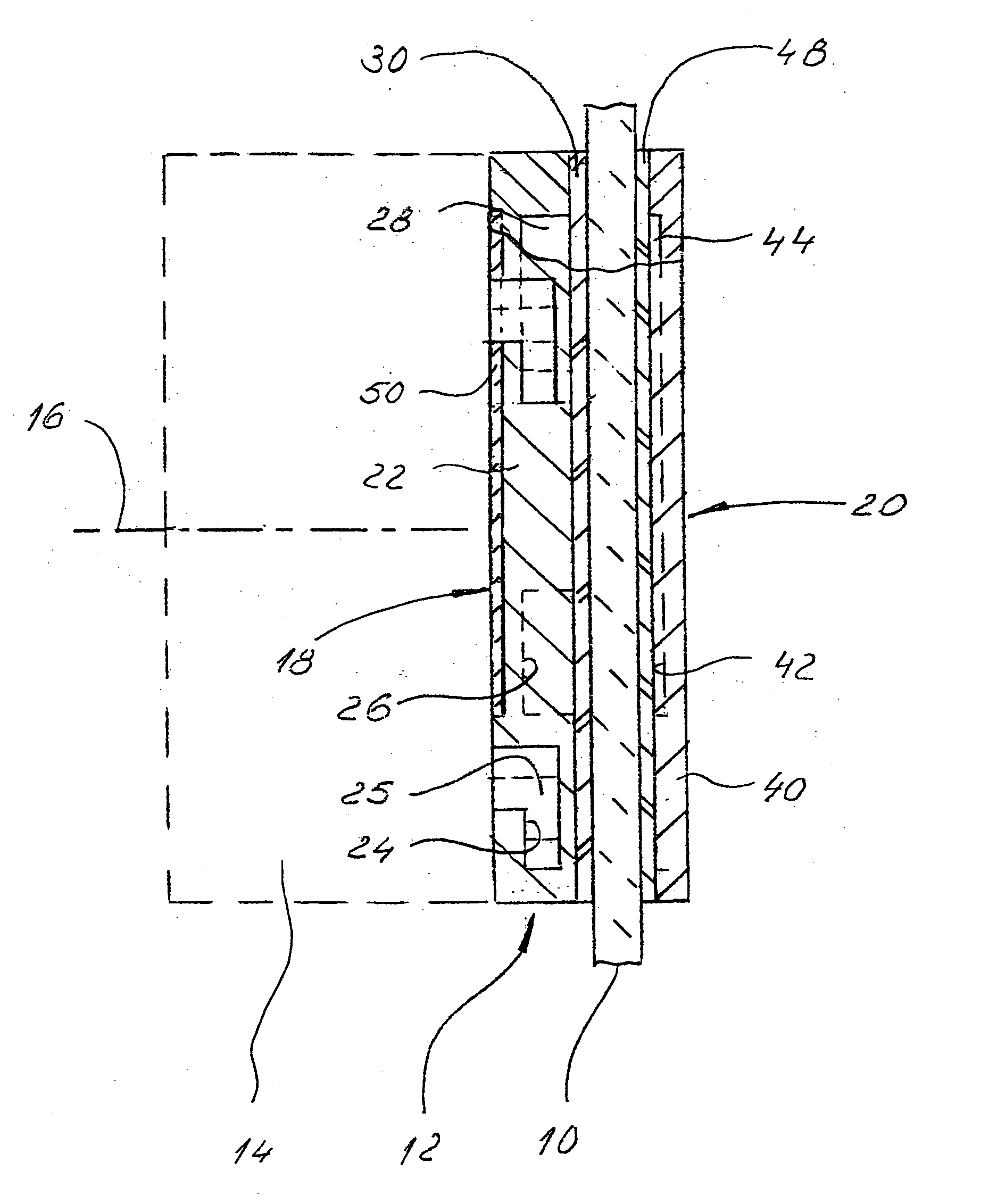
[0024] A glass pane which forms the rear wall of an aquarium (or even a side wall or front wall) is shown at 10 in FIG. 1. The water in the aquarium is to be imagined as being on the left of the glass pane 10.

[0025] Attached to the glass pane 10 via a magnet-holder, which is designated as a whole by 12, is a pump 14 which is a centrifugal pump with a horizontal axis of rotation which stands perpendicularly on the face of the glass pane 10. Said axis of rotation is indicated at 16.

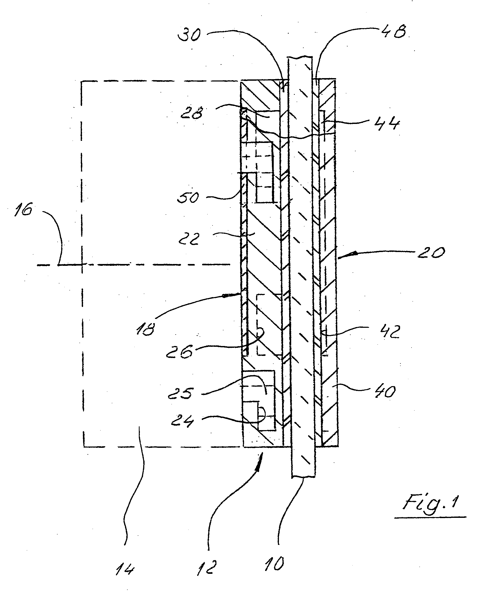
[0026] The magnet-holder 12 comprises an inner holding part which is designated as a whole by 18, and an outer holding part which is designated as a whole by 20.

[0027] The inner holding part 18 comprises a mounting plate 22 which is provided with bayonet-type apertures 24 in which corresponding bayonet-type parts 25 on the pump 14 can engage and which are represented diagrammatically in FIG. 1.

[0028] The mounting plate 22 also has four receiving apertures 26, in each of which a disc-shaped permanent mag...


PUM


Abstract

A magnet-holder for attaching an object to a glass pane has two parts of a holder which can be placed on mutually opposed boundary faces of said glass pane and are biased towards one another by a magnetic-force apparatus. In addition, that part of the holder which is disposed on the inner side of the glass pane has a contact plate whose side that faces towards the glass pane carries a plurality of elastic holding cups which can cling to the pane.

Description

BACKGROUND OF THE INVENTION [0001] The invention relates to a holder for attaching an object to a smooth pane. [0002] Holders of this kind, which serve to attach accessories to the panes of an aquarium, are obtainable on the market. They comprise a mounting plate which is provided with mechanical fastening means to which an appliance can be attached, for example by hooking in or screwing on. For its part, the base plate carries a plurality of permanent magnets which cooperate with a holding plate which is manufactured from magnetically conducting material and is fitted on the outside of the glass pane. [0003] In this way, the mounting plate and holding plate are pressed, by magnetic forces, against the mutually opposed surfaces of the glass pane. As a result of a frictional-contact connection between the cooperating surfaces of the mounting plate and glass pane, and the glass pane and holding plate, the holder is then seated firmly on the glass pane of the aquarium, even under the e...

Claims


Application Information

Patent Timeline
Patent Type & Authority Applications(United States)
IPC IPC(8): A47G1/17A01K61/00
CPCA01K61/003A01K63/10
Inventor TUNZE, AXEL
Owner TUNZE AQUARIENTECHN
Why Eureka
Try Eureka