Connection device

Active Publication Date: 2019-08-15
PHOENIX FEINBAU GMBH & CO KG
View PDF0 Cites 0 Cited by
  • Summary
  • Abstract
  • Description
  • Claims
  • Application Information

AI Technical Summary

Benefits of technology

The invention provides a way to connect a linear drive to a linearly guided slide element that makes it easy to compensate for alignment errors and lateral offsets between the drive and the output side. The mounting process is simple.

Problems solved by technology

The connection of this linear coupling to the drive and to the output takes place here both on the drive side and also on the output side via threaded joints so that mounting is relatively complex and a corresponding tool is necessary.
In these couplings, however, mounting is also relatively complex due to the screwing of the track ring elements into the housing.
In addition, lateral offset between the drive and output cannot be compensated with this coupling.

Method used


Image

  • Connection device
  • Connection device
  • Connection device

Examples


Embodiment Construction

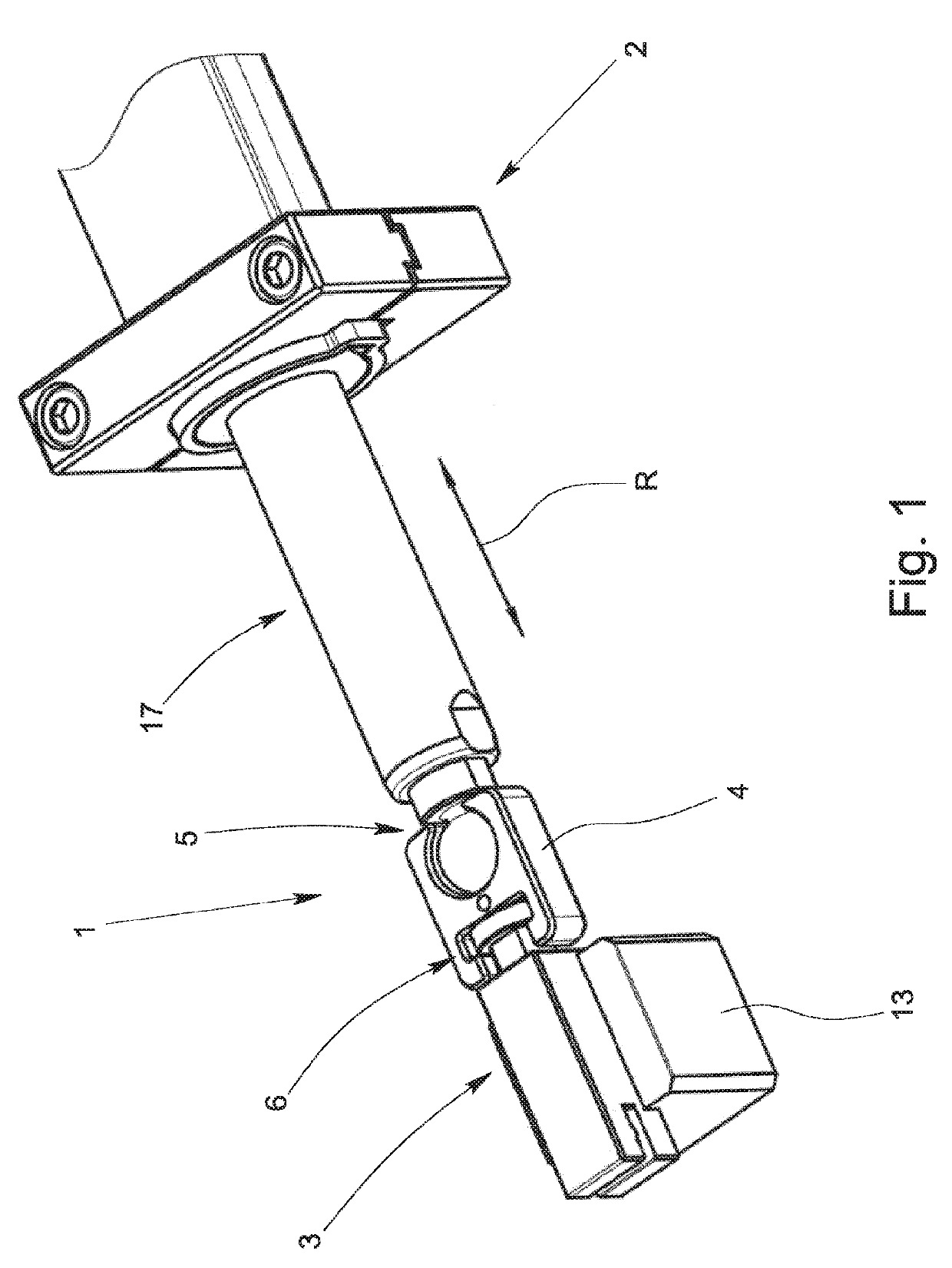
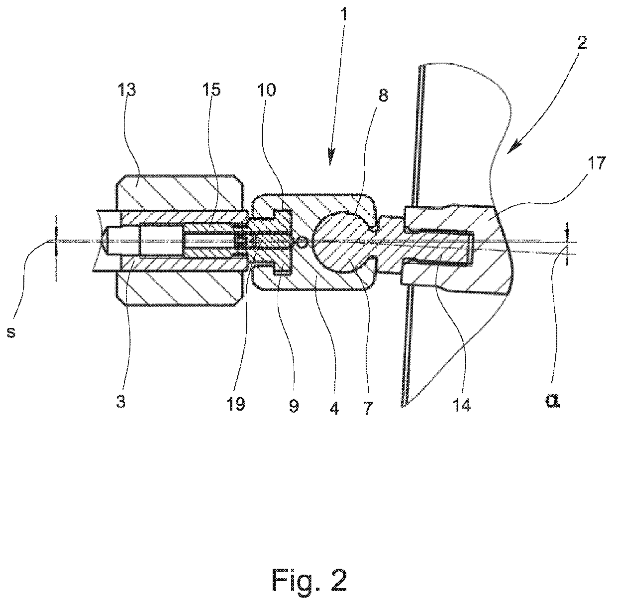
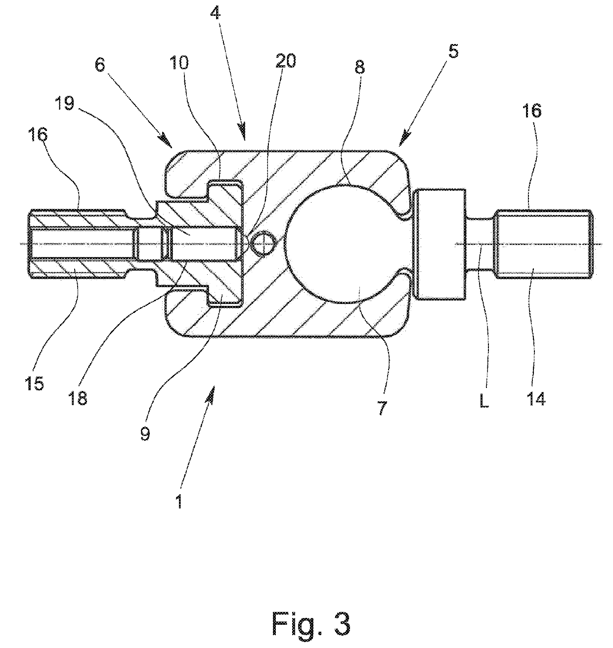
[0022]In the perspective view of FIG. 1, a coupling 1 for connecting a linear drive 2 to a linearly guided slide element 3 is shown. The coupling 1, which is shown separately in FIGS. 3, 5a and 5b, is comprised of a coupling center piece 4, a ball joint 5, and a prismatic joint 6, the ball joint 5 and the prismatic joint 6 being located on opposite sides of the coupling 1.

[0023]The ball joint 5 is comprised of a joint head 7 and a corresponding joint head socket 8. The prismatic joint 6 also has a joint head 9 and a corresponding joint head socket 10. The joint head socket 8 of the ball joint 5 and the joint head socket 10 of the prismatic joint 6 each have a socket space 11, 12 which is open on both sides perpendicular to the longitudinal axis L of the coupling 1. To join the joint head 5, the coupling center piece 4 thus need simply be pushed or slid onto the joint head 7 perpendicular to the direction of the linear motion R with the joint head socket 8. Accordingly, to join the p...


PUM


Abstract

A coupling (1) for connecting a linear drive (2) to a linearly guided slide element (3) having a coupling center piece (4), a ball joint (5) and a sliding joint (6). The ball joint (5) and the sliding joint (6) are arranged on opposite sides of the coupling (1). The ball joint (5) has a joint head (7) and a joint head socket (8), and the sliding joint (6) has a joint head (9) and a joint head socket (10). The joint head socket (8) of the ball joint (5) and / or the joint head socket (10) of the sliding joint (6) has / have a socket space (11, 12) which is open, at least on one side, perpendicularly to the longitudinal axis (L) of the coupling (1).

Description

BACKGROUND OF THE INVENTIONField of the Invention[0001]The invention relates to a coupling for connection of a linear drive to a linearly guided slide element.Description of the Related Art[0002]To connect a permanently mounted linear drive to a linearly guided slide element, for example, a punching tool, couplings are used which corresponding to the drive direction are also called linear couplings. For exact positioning of the slide element an axially rigid coupling as free of play as possible is necessary between the linear drive and the slide element. Moreover, the coupling should be able to compensate both for an alignment error and also an offset which occurs perpendicularly to the direction of the linear motion between the drive and the output, i.e., the slide element, as free of torque bias as possible.[0003]Practice discloses an axially play-free linear drive which on the drive side consists of a disk-shaped hub with a threaded journal and on the output side of a disk-shaped...

Claims


Application Information

Patent Timeline
IPC IPC(8): F16C11/06
CPCF16C11/0695F16C11/06F16D3/16
Inventor GRUSS, DOMINICNOLDA, THORSTEN
Owner PHOENIX FEINBAU GMBH & CO KG
Why Eureka
Try Eureka