Small engine fuel tank with integrated evaporative controls
- Summary
- Abstract
- Description
- Claims
- Application Information
AI Technical Summary
Benefits of technology
Problems solved by technology
Method used
Image
Examples
Embodiment Construction
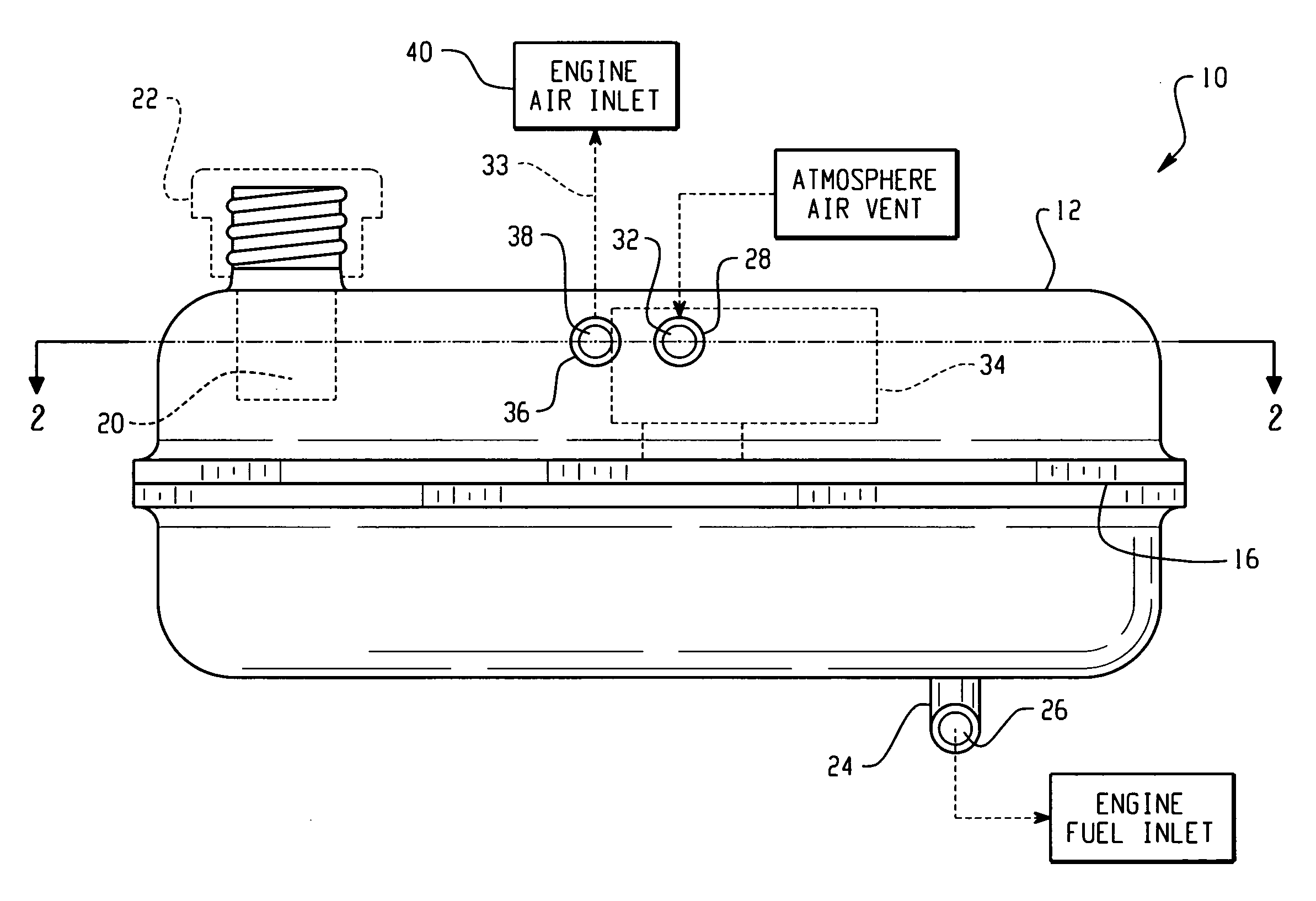
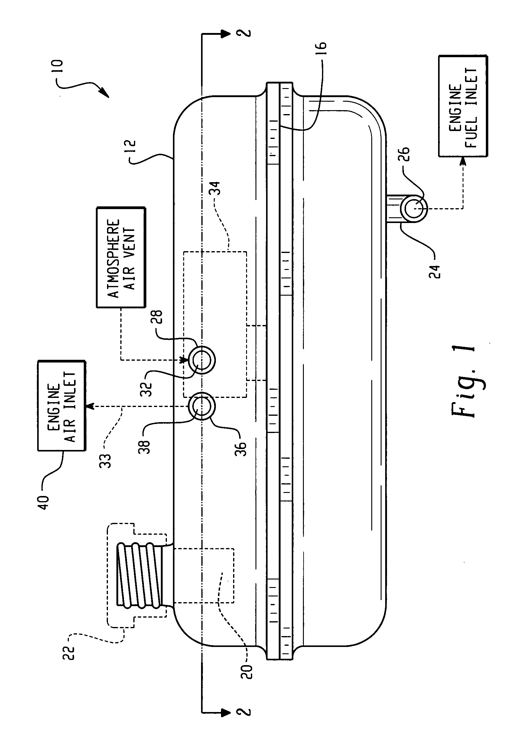
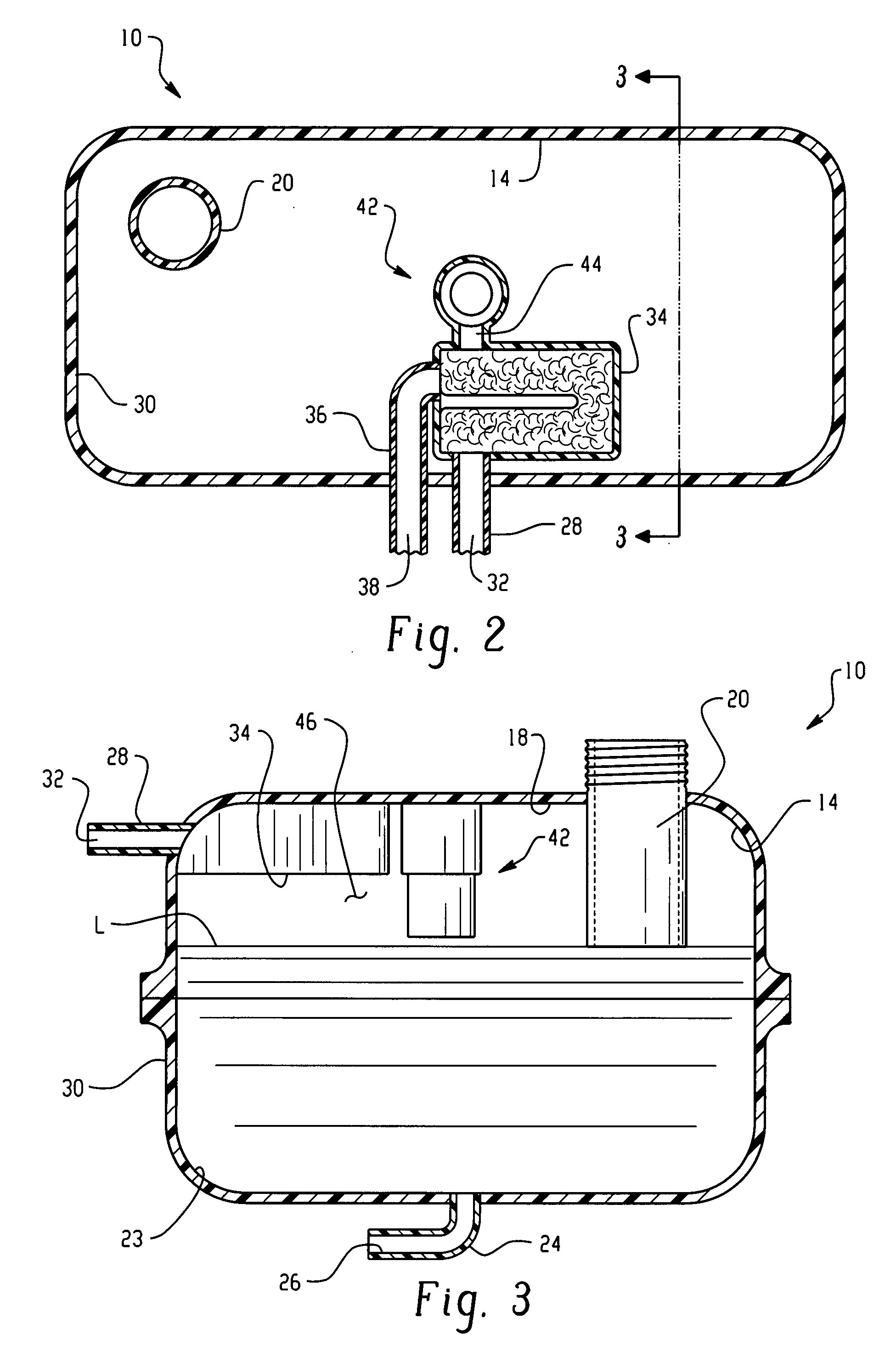
[0008] Referring to the drawings, the fuel tank assembly of the present invention is indicated generally at 10 and includes a tank 12 having wall structure 14 which may be formed conveniently by weldment about a mid-seam 16 in any manner well known in the art as, for example, by metallic or non-metallic welding as the case may be for the particular material employed for the tank.
[0009] The upper wail 18 of the tank has provided therein a filler tube 20 which may be integrally formed with the upper wall 18 and which is adapted for receiving thereover a closure cap 22 indicated in dashed outline in FIG. 1. The tube 20 extends downwardly into the interior of the tank to a desired depth for creating a vapor dome in the region beneath the upper wall 18 when the liquid level in the tank has risen to cover the lower end of tube 20.
[0010] Tank 12 has a fuel feed outlet fitting 24 provided through the lower wall on the lower wall thereof with a fuel feed passage 26 formed therein for gravi...
PUM
 Abstract
Description
Claims
Application Information
 - R&D
- Intellectual Property
- Life Sciences
- Materials
- Tech Scout
- Unparalleled Data Quality
- Higher Quality Content
- 60% Fewer Hallucinations
Browse by: Latest US Patents, China's latest patents, Technical Efficacy Thesaurus, Application Domain, Technology Topic, Popular Technical Reports.
© 2025 PatSnap. All rights reserved.Legal|Privacy policy|Modern Slavery Act Transparency Statement|Sitemap|About US| Contact US: help@patsnap.com


