Free-form lenses for rectangular illumination zones

a free-form, rectangular technology, applied in the field of illumination, can solve the problems of incompatibility with the rectangular geometry, global discontinuities, segmented lenses with radial cliffs, etc., and achieve the effect of high efficiency

Active Publication Date: 2010-03-09
ANTHONY INC
View PDF10 Cites 47 Cited by
  • Summary
  • Abstract
  • Description
  • Claims
  • Application Information

AI Technical Summary

Problems solved by technology

Accordingly, the surface integration must be done in spherical coordinates, which creates an incompatibility with the rectangular geometry of the target zone because spherical rectangles cannot totally cover hemispheres.
The challenge of this geometry is the cos−3 dependence of intensity, which requires 25 times more intensity towards the edge of the pattern and 82 times more intensity towards the corners of the pattern than is required just in front of the lens, the on-axis direction towards which an LED with no lens would have its maximum candlepower.
The greatest challenge of such lenses is that the required output intensity distribution for uniform illumination of a planar target, when expressed in the spherical geometry of the hemispheric emission of light, leads to a distribution of surface normals that is not integrable.
Nonetheless, global discontinuities in the form of abrupt cliffs can result from many well-behaved surfaces, such as the screw shapes (i.e., helicoids).
Strict adherence to integrability could result in segmented lenses with radial cliffs, an undesirable configuration from both manufacturing and performance standpoints.

Method used


Image

  • Free-form lenses for rectangular illumination zones
  • Free-form lenses for rectangular illumination zones
  • Free-form lenses for rectangular illumination zones

Examples


Embodiment Construction

[0043]A better understanding of the features and advantages of the preferred methods and embodiments disclosed herein will be obtained by reference to the following detailed description of the preferred embodiments and accompanying drawings, which set forth illustrative embodiments in which the principles of the invention are utilized.

[0044]The design of refractive free-form illumination optics will encounter a fundamental difficulty when large solid angles are involved, particularly in the case of light-emitting diodes (LEDs), which emit into a hemisphere. There is a topological mismatch between a rectangular target and the hemispheric or quasi-hemispheric (60° or more off-axis) emission of most LEDs.

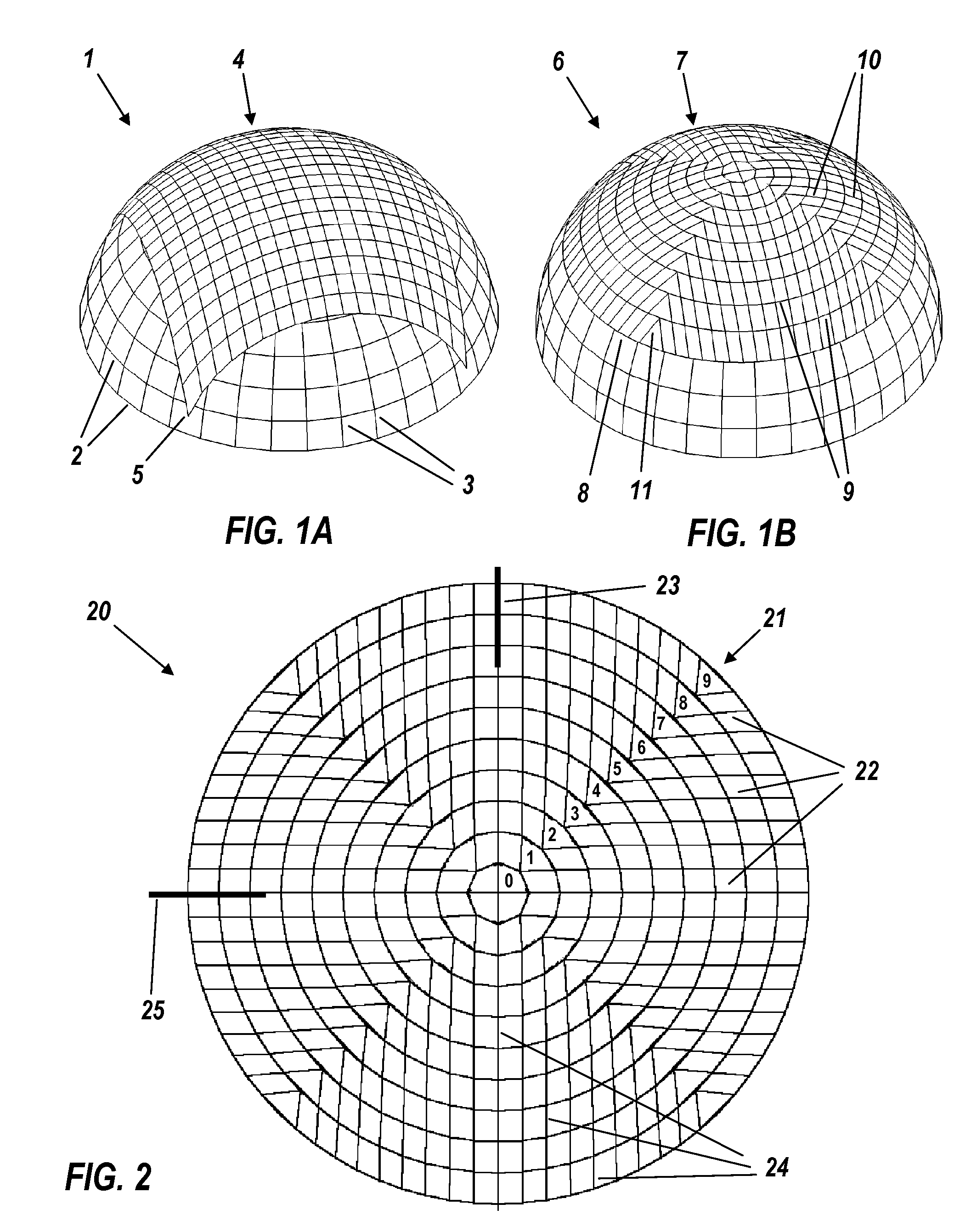
[0045]FIG. 1A illustrates a unit-radius spherical cap 1 that represents the angular coverage of an LED emitting out to 60° off-axis. The cap 1 has a polar grid comprising co-latitude circles 2 extending to 60° off-axis and meridians 3. A rectangular grid 4 is overlaid upon the cap 1 wi...


PUM


Abstract

A light source emits light into a solid angle exceeding pi steradians with a known intensity distribution. An illumination lens has a first surface that receives at least 90% of the light of the known intensity distribution and has a shape that transforms the known intensity distribution into an intermediate intensity distribution within the transparent material of the lens. A second surface receives the intermediate intensity distribution and is shaped to transform the intermediate intensity distribution into a final intensity distribution that produces a prescribed illumination distribution upon a rectangular target zone. At least one of the shapes of the first and second surfaces is non-rotationally symmetric and is approximated by a super-ellipsoid.

Description

RELATED APPLICATIONS[0001]The present application claims priority under 35 USC § 119(e) to U.S. Provisional Application No. 60 / 955,340 filed on Aug. 11, 2007, U.S. Provisional Application No. 61 / 046,448 filed on Apr. 20, 2008, and U.S. Provisional Application No. 61 / 050,619 filed on May 5, 2008, which are incorporated by reference herein.BACKGROUND OF THE INVENTION[0002]1. Field of the Invention[0003]The present invention is generally in the field of illumination using electrical energy, and, more particularly, is in the field of illumination utilizing light-emitting diodes (LEDs).[0004]2. Description of the Related Art[0005]Solid-state lighting promises to become the major light source of the near future, not only to save energy but also because the small size and the high efficiency of LEDs promote far more versatility of applications than did previous lighting technology. This in turn has stimulated the field of illumination optics, which previously was nearly all reflective, wit...

Claims


Application Information

Patent Timeline
Patent Type & Authority Patents(United States)
IPC IPC(8): F21V5/00
CPCF21V5/04G02B27/0955G02B19/0066G02B19/0014F21W2131/103F21Y2101/02F21Y2115/10
Inventor PARKYN, WILLIAM A.PELKA, DAVID G.
Owner ANTHONY INC
Why Eureka
Try Eureka