
Manufacturing system and manufacturing method for sheet-like structure

a manufacturing system and sheet-like technology, applied in the direction of hand sewing, sewing machine elements, bandages, etc., can solve the problems of menstrual blood leakage through the free end side of the extended portion through the free end side of the extended portion, and the above thread coming off cannot be completely prevented

Inactive Publication Date: 2010-03-16
UNI CHARM CORP
View PDF17 Cites 45 Cited by
  • Summary
  • Abstract
  • Description
  • Claims
  • Application Information

AI Technical Summary

Benefits of technology

[0015]The arranging apparatus arranges each of the plural sheet members so as to be in contact with each of the plural linear portions formed by the loosened portion forming apparatus. By arranging as above, continuous sewing by a sewing apparatus as described below becomes possible.
[0050]According to the method for manufacturing a sheet-like structure, the sheet member is a sheet-like absorbing member comprising a specified absorbing layer with liquid absorbability coated with a surface material of thin film form, and the method for manufacturing sheet-like structures further comprises forming a sheet-like member in which the surface material is applied to the absorbing layer. This allows a sheet-like absorbing member to be formed by applying a surface material to the fibrous absorbing layer for preventing unraveling of the fibrous absorbing layer, and enables the above-mentioned cord member to be sewn onto the absorbing member formed in a sheet-like form.

Problems solved by technology

This has caused problems in that, for example, the thread member starts to come off from free ends of the cord member in the sheet-like structures causing the thread member sewn onto the sheet member to also come off.
However, the above thread coming off cannot be prevented completely in the absorbing member of Patent Document 1 because the thread member runs from the sheet member to the cord member continuously.
Also, when this is used as an absorbing member for tampons, menstrual blood may leak from the free end side of the extended portion through the thread.
Consequently, this still offer problems in that the thread is used more than necessary and the step of sewing requires excessive time.

Method used


Image

  • Manufacturing system and manufacturing method for sheet-like structure
  • Manufacturing system and manufacturing method for sheet-like structure
  • Manufacturing system and manufacturing method for sheet-like structure

Examples


second embodiment

(2) Second Embodiment

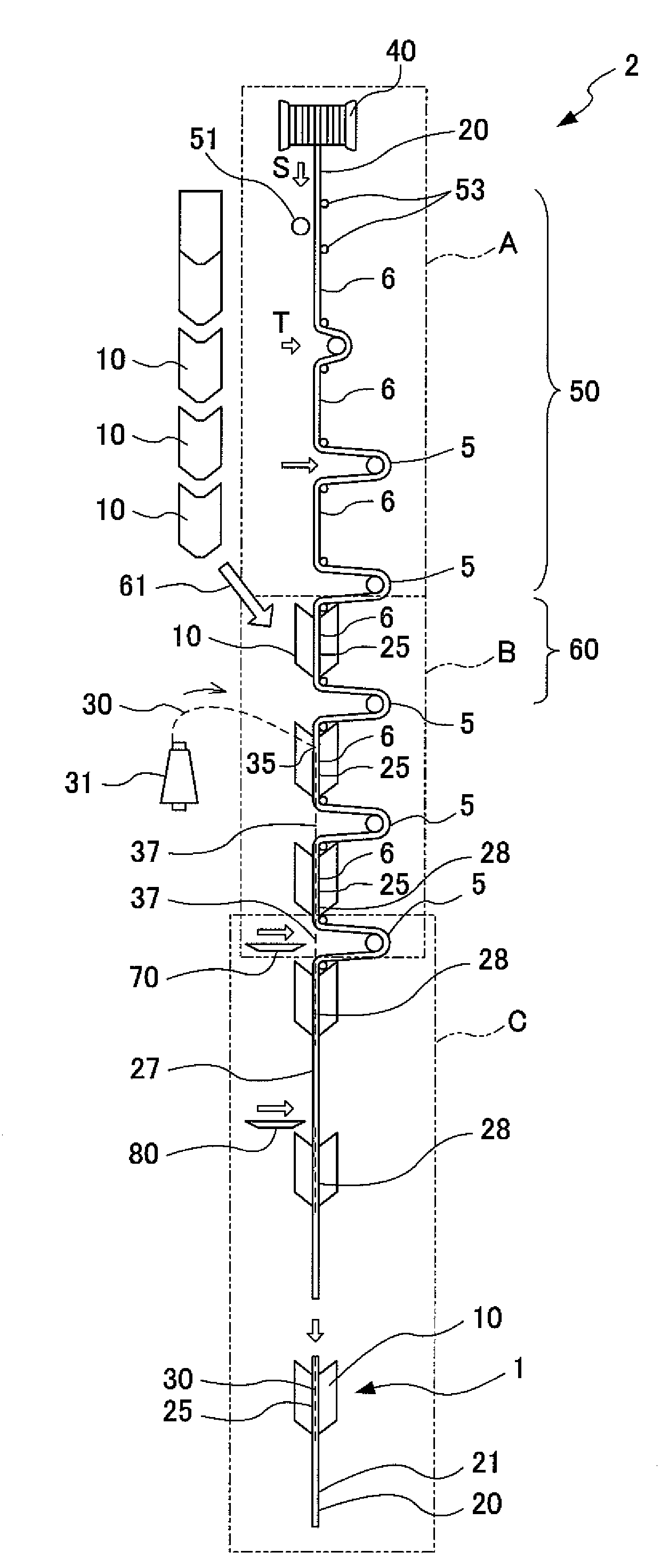
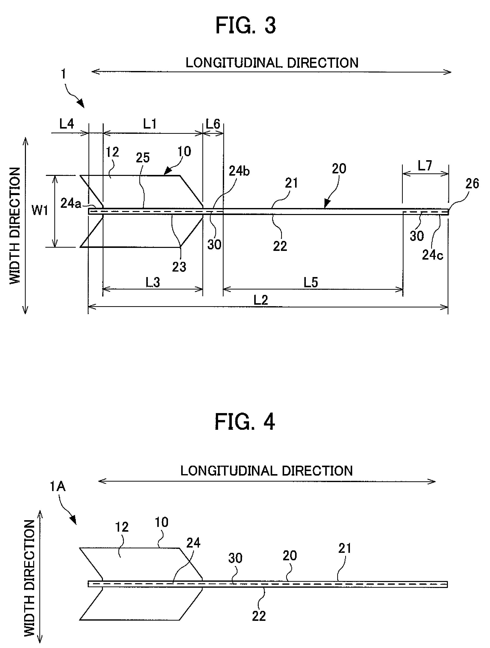
[0108]As shown in FIG. 11, a manufacturing system for sheet-like structures 2A in the second embodiment is a system by which a sheet-like structure 1 as shown in FIG. 3 is manufactured. Specifically, the sheet-like structure 1 is a sheet-like structure in which a sewn area 24c is formed on a free end 26 of the extended portion 21.

[0109]Although the manufacturing system of sheet-like structures 2A in the second embodiment is similar to the manufacturing system of sheet-like structures 2 in the first embodiment, it differs in the length L of the linear portion 6. Specifically, the length L of the linear portions 6 of the manufacturing system 2A in the second embodiment is set longer than the length of the linear portions 6 of the manufacturing system 2 in the first embodiment.

[0110]In other words, a sewn area 28 is formed on one side of the absorbing member 10 in the second embodiment because the length L of the linear portion 6 is set longer than the length L1 of...

third embodiment

(3) Third Embodiment

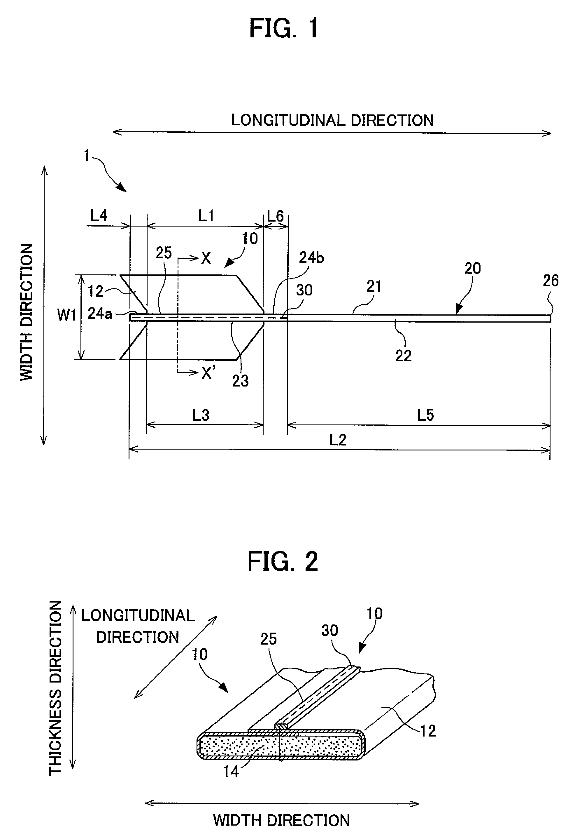
[0112]As shown in FIG. 12, a manufacturing system of sheet-like structures 2B in the third embodiment is a system by which the sheet-like structure 1 as shown in FIG. 1 is manufactured.

[0113]Although the manufacturing system of sheet-like structures 2B in the third embodiment is similar to the manufacturing system of sheet-like structures 2 in the first embodiment, it differs in the direction of the absorbing member 10. Specifically, the absorbing member 10 of the manufacturing system 2 in the first embodiment is manufactured while the convex side of the feather-like form is turned to the direction S, which is a traveling direction, whereas the absorbing member 10 of the manufacturing system 2B in the third embodiment is manufactured while the convex side of the feather-like form is turned to a direction opposite of the direction S, which is a traveling direction.

[0114]In addition, positions at which the cord connecting portions 27 formed so as to connect a speci...

fourth embodiment

(4) Fourth Embodiment

[0115]As shown in FIG. 13, a manufacturing system of sheet-like structures 2C in the fourth embodiment is a system in which a sheet-like structure 1 as shown in FIG. 3 is manufactured. The sheet-like structure 1 is a sheet-like structure in which a sewn area 24c is formed on a free end 26 of the extended portion 21.

[0116]Although the manufacturing system of sheet-like structures 2C in the fourth embodiment is similar to the manufacturing system of sheet-like structures 2A in the second embodiment, it differs in the direction of the absorbing member 10. Specifically, the absorbing member 10 of the manufacturing system 2A in the second embodiment is manufactured while the convex side of the feather-like form is turned to the direction S, which is a traveling direction, whereas the absorbing member 10 of the manufacturing system 2C in the fourth embodiment is manufactured while the convex side of the feather-like form is turned to a direction opposite of the direct...


PUM


Abstract

An object of the present invention is to provide a manufacturing system and a method for manufacturing sheet-like structures. The manufacturing system of sheet-like structures contains a loosened portion forming apparatus by which plural loosened portions, which are substantially U-shaped, are formed on a cord member, and plural linear portions, which connect each of the plural loosened portions, are formed substantially linearly; and a sewing apparatus by which each of the plural absorbing members and each of the plural linear portions are sewn with a thread member.

Description

[0001]This application is based on and claims the benefit of priority from Japanese Patent Application No. 2006-024399, filed on Feb. 1, 2006, the content of which is incorporated herein by reference.BACKGROUND OF THE INVENTION[0002]1. Field of the Invention[0003]The present invention relates to manufacturing systems and methods for manufacturing sheet-like structures comprising sheet members with prescribed forms and predefined cord members.[0004]2. Related Art[0005]Conventionally, in sewing sheet-like structures in which predefined cord members are sewn onto sheet members of a prescribed form, cord members and the sheet members are sewn together in a longitudinal direction of the cord members in order to sew the cord members and sheet members firmly. When a large quantity of sheet-like structures are manufactured continuously for example, a cord member is reeled out linearly and sewn continuously with a thread while plural sheet members are arranged at predetermined intervals so a...

Claims


Application Information

Patent Timeline
Patent Type & Authority Patents(United States)
IPC IPC(8): D05B3/00A61F13/34D05B27/00
CPCA61F13/2085
Inventor KONDO, HIDEKIHOSOKAWA, MASASHI
Owner UNI CHARM CORP
Learn More