Plug connector having retainer attached mold case

Inactive Publication Date: 2010-03-16
HONDA TSUSHIN IND
View PDF10 Cites 12 Cited by
  • Summary
  • Abstract
  • Description
  • Claims
  • Application Information

AI Technical Summary

Benefits of technology

[0009]Hence, in view of the above-described problem in the prior art, it is an object of the invention to provide a retainer attached mold case that prevents an elastic claw from being damaged in fitting the elastic claw by preventing the elastic claw from floating up and preventing a retainer from being opened and damaged.
[0012]It is preferable that engaging portions projected to inner sides of the mold case for engaging with the insulating member are respectively provided on upper and lower sides of an opening edge portion of a front end of the mold case, a front end portion of the insulating member is formed with guide grooves respectively engaged with the engaging portions, and an upper portion and a lower portion of the mold case divided by the slit are prevented from being opened in an up and down direction.
[0013]According to the retainer attached mold case of the invention, the locking projection is projected to the rear side from the rear end portion of the elastic claw, the float preventing piece for preventing the elastic claw from floating up by engaging with the locking projection is projected from the front end portion of the retainer, and therefore, the elastic claw does not float up and is not damaged even when forcibly screwed in while being fitted.
[0014]Further, the engaging grooves extended in the front and rear direction are formed at the inner wall faces of the upper portions of the two side walls of the mold case at the elastic claw, the engaging portions fitted to the engaging grooves are formed to project horizontally at the two side faces of the float preventing piece, and therefore, even when a rapid force by the cable is exerted to the opening edge portion, the retainer per se is not damaged by opening the retainer.

Problems solved by technology

Therefore, the elastic claw 102 cannot be completely prevented from floating up.
However, a lower portion 104 of the mold case 100 may become damaged when in a case in which the cable attached plug connector “A” is caught thereby and cannot be smoothly inserted upon insertion of the cable attached plug connector “A” from the opening portion of the insulating member 109, the cable attached plug connector “A” is forcibly screwed in.
Further, also in the retainer 105, there is a problem that when a rapid force is exerted to an opening edge portion thereof by the cable 106, the retainer 105 is opened and the retainer per se is damaged.

Method used


Image

  • Plug connector having retainer attached mold case
  • Plug connector having retainer attached mold case
  • Plug connector having retainer attached mold case

Examples


Embodiment Construction

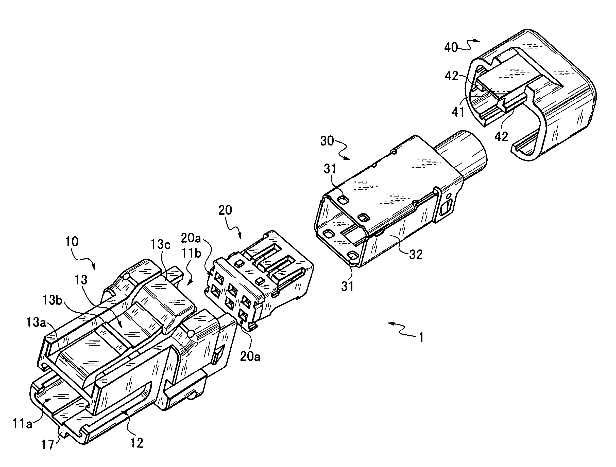
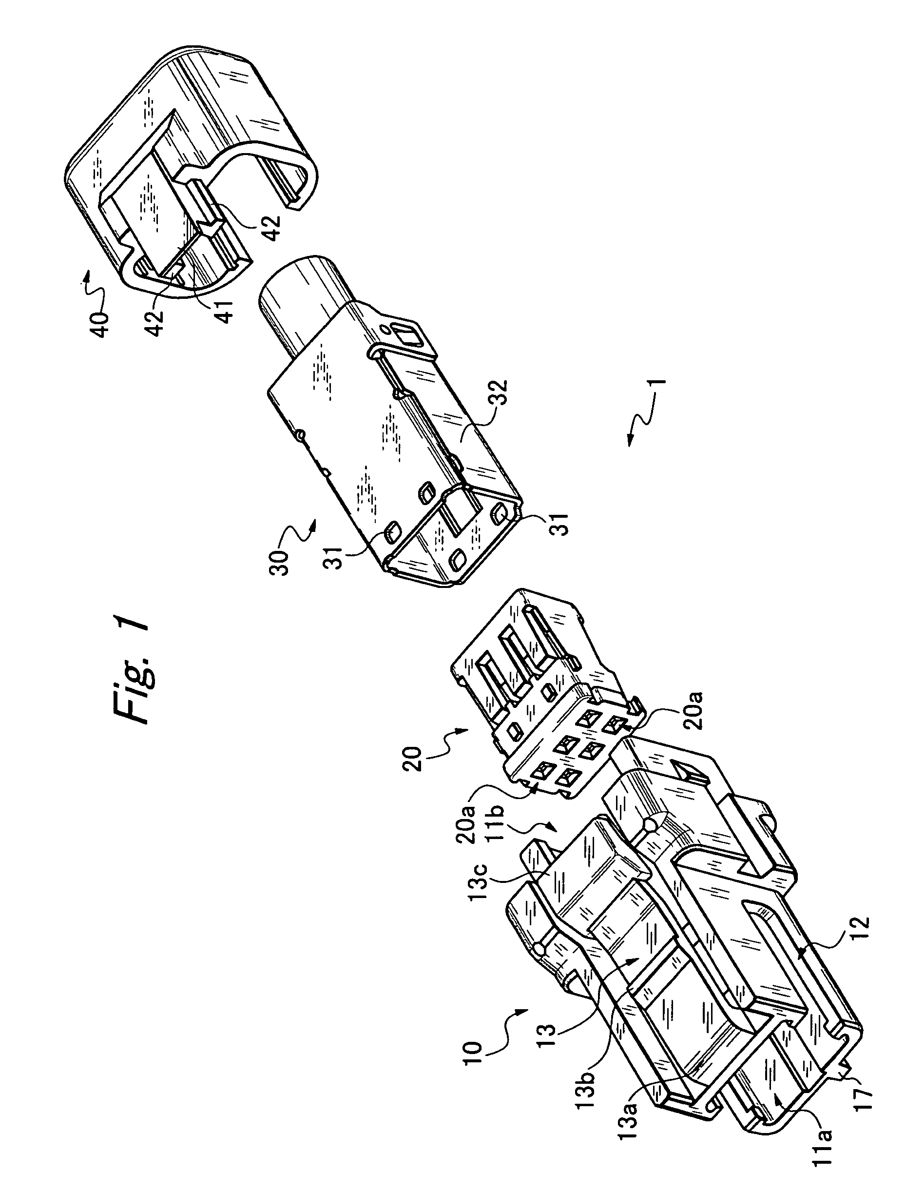
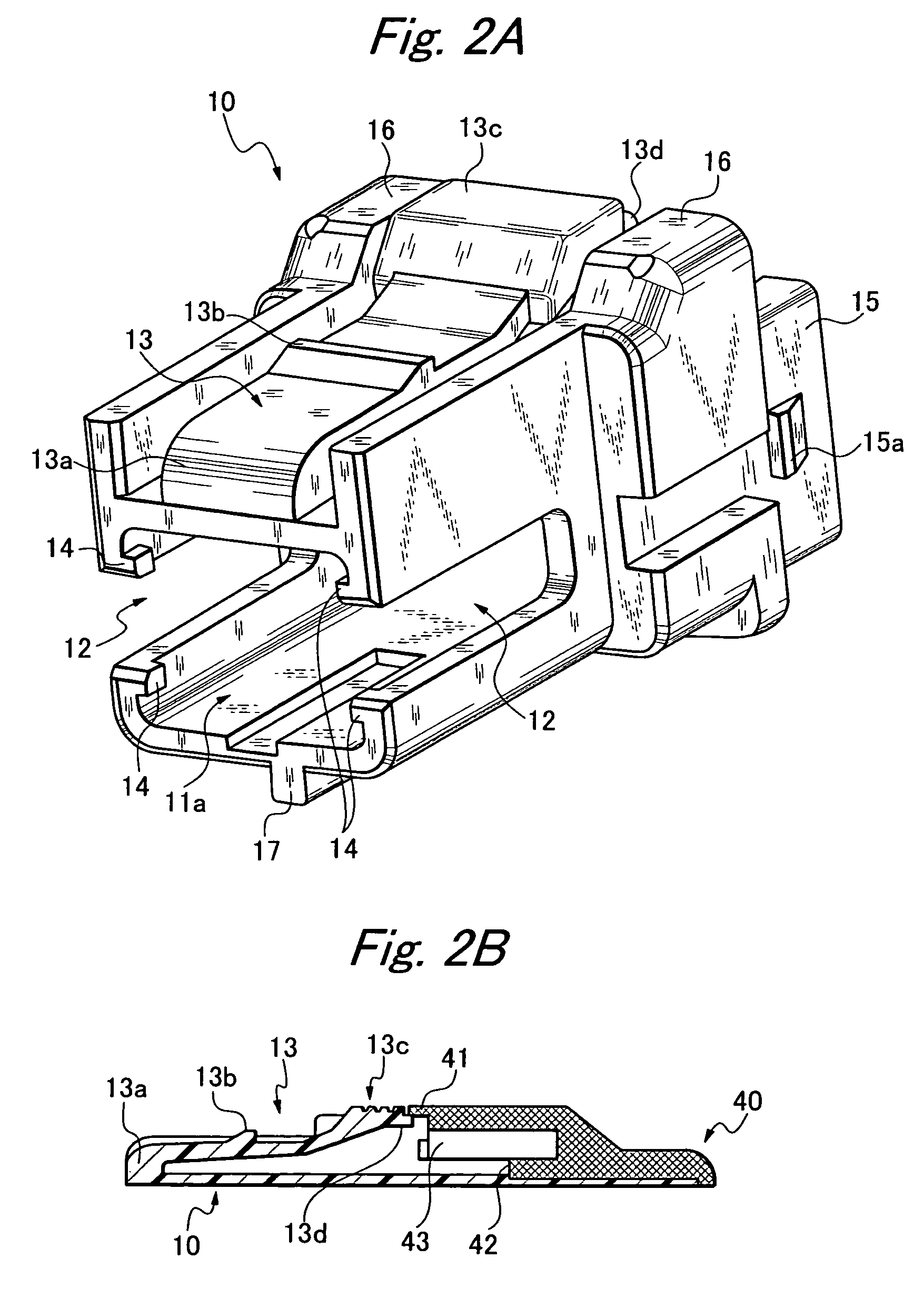
[0030]As shown in FIG. 1, a plug connector 1 according to an embodiment of the invention is constituted by a mold case 10, an insulating member 20 aligned with containing holes 20a containing female contacts (not illustrated), a shield case 30 surrounding the insulating member 20 excluding a front face thereof, and a retainer 40 closing a rear end opening 11b of the mold case 10 excluding a cable inserting portion. The mold case 10 has a substantially cylindrical shape with an inner space portion that accommodates the shield case 30 and insulating member 20.

[0031]As shown in FIGS. 2A and 2B, two side walls of the mold case 10 are formed with grounding slits 12, 12 for that communicate with a front end opening 11a. An upper face of the mold case 10 is formed in a recess shape and is provided with an elastic claw 13 extended to a rear side by being turned back from a front end portion 13a. Four portions of an edge portion of the opening 11a are respectively formed with engaging portio...


PUM


Abstract

To prevent damage by an external force in a retainer attached mold case of a plug connector including an insulating member having aligned containing holes containing contacts, a shield case surrounding the insulating member, a substantially cylindrical mold case incorporating these therein and having slits for grounding at two side walls thereof and an elastic claw with a lock portion and a lock release portion at an upper face, and a retainer for closing a rear end opening of the mold case excluding a cable inserting portion, a locking projection is projected to a rear side from a rear end portion of the elastic claw, and a float preventing piece for preventing the elastic claw from floating up by engaging with the locking projection is projected from a front end portion of the retainer.

Description

BACKGROUND OF THE INVENTION[0001]1. Field of the Invention[0002]The present invention relates to a plug connector including a mold case, for use with a wire harness or the like of an automobile.[0003]2. Prior Art[0004]In a prior art configuration, as shown in FIG. 10, a plug connector “A” attached with a cable of a wire harness or the like is constituted by a rectangular slender mold case 100, and a retainer 105 mounted to a rear portion of the mold case. A cable 106 has a plurality of core wires connected to a female contact of an insulating member 107 fixedly attached to inside of the mold case and led out to a rear side of the mold case. The mold case 100 is provided with a slit 101 at a side wall thereof, and a portion of a shield case 103 surrounding the insulating member 107 at an inside thereof is exposed to the outside. Further, an upper portion of the mold case is provided with an elastic claw 102 for connection locking, a projection 102a for locking, and a press portion 10...

Claims


Application Information

Patent Timeline
IPC IPC(8): H01R13/46
CPCH01R13/506H01R13/6272H01R13/6583H01R2201/26
Inventor SATO, TAKESHIKAWANO, TAKU
Owner HONDA TSUSHIN IND
Why Eureka
Try Eureka